The Josephson Transmission Line (JTL) cell
BACK to the SFQ GENERATOR explanation
BACK to the DCSFQ cell explanation
At a glance
| Property | Value |
|---|---|
| Cell name | JTL |
| Function | Josephson Transmission Line — buffers and reshapes each SFQ pulse, passing one fluxon per junction towards the output |
| Josephson junctions | 2 (B1, B2) |
| Junction models used | JJ250 ×2 (B1, B2) |
| Internal bias source | 1 (IPWL1) |
| Inductors | 6 (L1, L2, L3, L4 on the signal path; L1p, L2p parasitic) |
| Damping resistors | 2 (RB1, RB2) |
| Total device count | 11 |
| Ports | 2 (INPUT = port 1, OUTPUT = port 2) |
| Series inductances | L1 = L2 = L3 = L4 = 2 pH (inter-junction loop ≈ 4 pH) |
| Josephson inductance | LJ0(B1, B2) ≈ 1.32 pH (same as B3 of the DCSFQ cell) |
| Simulators supported | JSIM, JoSIM |
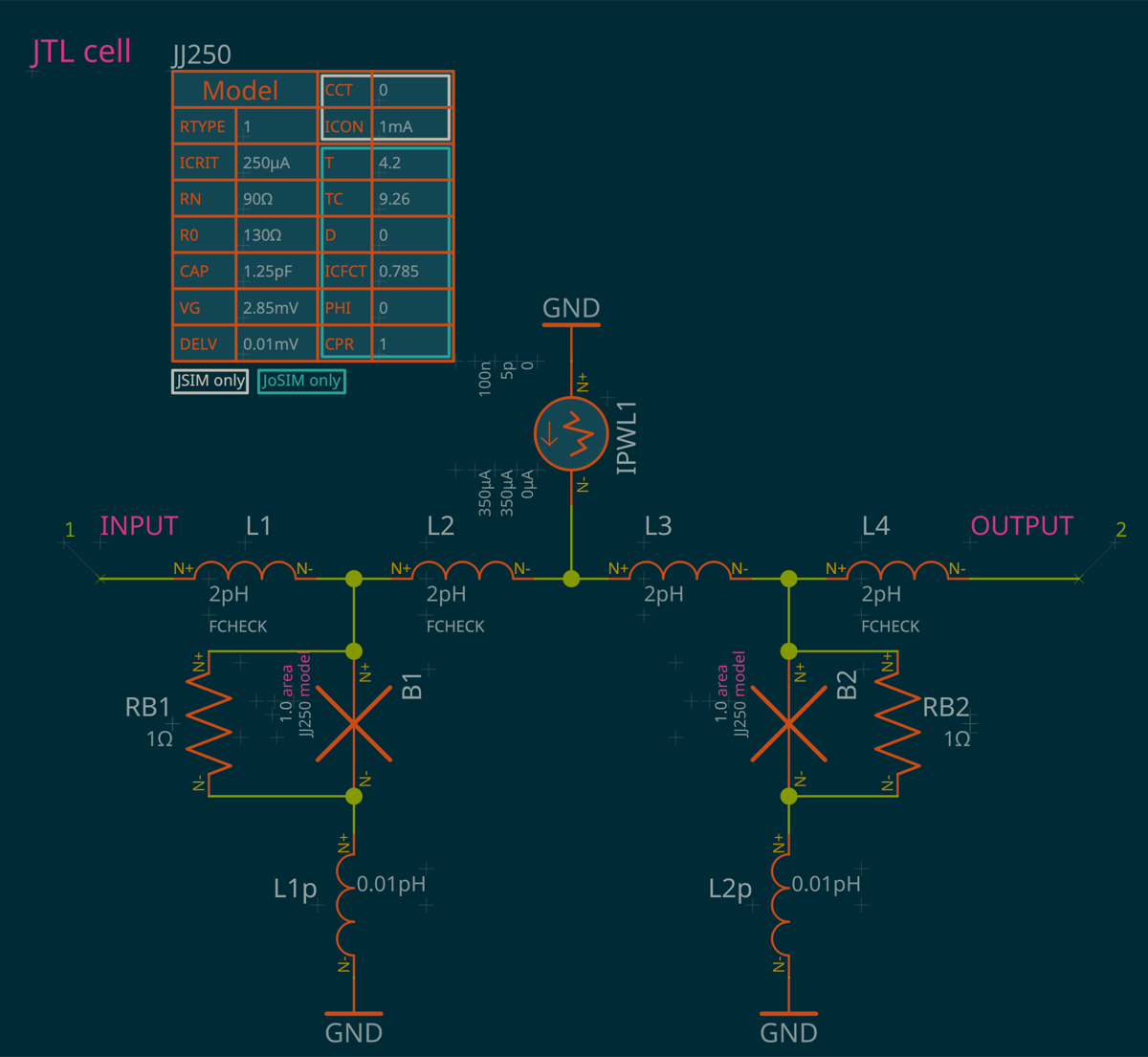
The two evenly-biased JTL cells placed in series after the DCSFQ cell act as buffers and perform the same role as B3 of the DCSFQ cell. Each JTL junction therefore has the same critical current — and hence the same Josephson inductance — as B3. The loops inside the cell have an inductance of about 4 pH, comparable to L4 in the DCSFQ cell, and the loop formed by two consecutive JTL cells (B2–L4–L1–B1 of the next cell) also has an inductance of about 4 pH. Overall, the five Josephson junctions placed in series (B3 of the DCSFQ cell plus the two junctions of each JTL cell) effectively decouple the output of the SFQ generator from the events occurring at the input of the DCSFQ cell.
Bias
| Source | Feeds | Current / waveform | Role |
|---|---|---|---|
| IPWL1 | mid-cell node between L2 and L3 | PWL 0 → 350 µA (rise over 0–5 ps, held to 100 ns) | Symmetric bias for B1 and B2, set so each junction reliably passes the incoming fluxon to the next stage |
IPWL1 is a piecewise-linear current source: current ramps from 0 to 350 µA between t = 0 and t = 5 ps, then stays constant up to 100 ns.
Junction models used
| Parameter | JJ250 |
|---|---|
| ICRIT | 250 µA |
| RN | 90 Ω |
| R0 | 130 Ω |
| CAP | 1.25 pF |
| VG | 2.85 mV |
| DELV | 0.01 mV |
| T | 4.2 K |
| TC | 9.26 K |
| Used by | B1, B2 |
The model also carries simulator-specific fields — CCT, RTYPE, ICON for JSIM and ICFCT, PHI, CPR, D for JoSIM — since the two simulators expect slightly different model syntax.
BACK to the SFQ GENERATOR explanation
BACK to the DCSFQ cell explanation
Copyright (C) 2025-2026 SEFIRA. Licensed under the Apache 2.0 license.