Reference guide – v0.3 – 06.09.2026¶
Part I — Concepts & conversion¶
1. Superconductor Library¶
The Superconductor library is dedicated to the LibrePCB schematic editor. It provides the devices, models and control commands needed to simulate digital and quantum superconducting electronics circuits with either the JoSIM or the JSIM simulator.
Every component is designed to map onto the netlist syntax of JSIM, of JoSIM, or of both. Where a component (or one of its attributes) is understood by only one simulator, this is stated explicitly in the tables below and marked with a badge:
| Badge | Meaning |
|---|---|
  |
Native support in that simulator. |
  |
Not supported. On conversion the component (or attribute) is dropped or converted; a #WARNING! / *ERROR! comment is written to the netlist. |
  |
Present in the library but not yet wired into the tool-chain. |
2. Component categories & conversion¶
An overview of the different library components is shown below.
2.1. Components overview¶
| Category | Components |
|---|---|
| Josephson Junctions | Josephson Junction, Josephson Junction With Quasiparticles, Model |
| Measurement Devices | Ammeter, Voltmeter, Voltage Probe, Phasemeter, Phase Probe, Subcircuit Multimeter |
| Passive Components | Capacitor, Resistor, Inductor, Mutual Inductor |
| Signal Sources | – |
| ├─ Current Sources | Current DC, Current AC, Current PWL, Current PWS, Current Pulse, Current Noise, Current Relaxation, Current Custom Waveform |
| ├─ Phase Sources | Phase DC, Phase AC, Phase PWL, Phase PWS, Phase Pulse, Phase Noise, Phase Relaxation, Phase Custom Waveform |
| └─ Voltage Sources | Voltage DC, Voltage AC, Voltage PWL, Voltage PWS, Voltage Pulse, Voltage Noise, Voltage Relaxation, Voltage Custom Waveform |
| Dependent Signal Sources | Voltage-Controlled Voltage Source, Voltage-Controlled Current Source, Current-Controlled Voltage Source, Current-Controlled Current Source |
| SPICE Commands | Transient Analysis, .PARAM, Model, Comments |
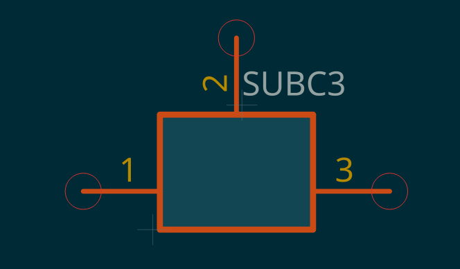
| Subcircuits | Subcircuit 1 port, Subcircuit 2 ports, Subcircuit 3 ports, Subcircuit 4 ports, Subcircuit 6 ports, Subcircuit 8 ports |
| Transmission Lines | Transmission Line |
| InductEx | Port |
The Model component belongs to both the Josephson Junction and the SPICE Command categories: it is a .MODEL control block that only makes sense next to a junction.
2.2. Symbols overview¶
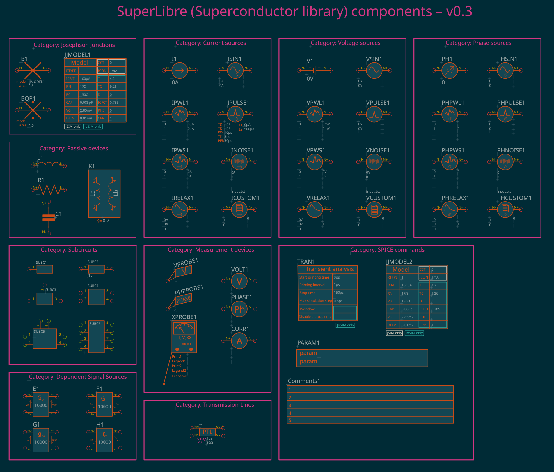
The corresponding symbols of the components are shown below.
2.3. Signal Sources¶
The library includes current, voltage and phase sources. Each is available in eight predefined subtypes, distinguished by their underlying waveforms and associated mathematical equations:
| Subtype | Waveform | JSIM | JoSIM |
|---|---|---|---|
| DC | Constant amplitude | ❌ (converted to a 2-point PWL by L2SPICE) | ✅ |
| AC | Damped sinusoid | ✅ | ✅ |
| PWL – Piece-Wise Linear | Straight segments between breakpoints | ✅ | ✅ |
| PWS – Piece-Wise Sinusoidal | Half-cosine segments between breakpoints. New in v0.3. | ❌ | ✅ |
| Pulse | Train of pulses, or a single pulse (JoSIM: leave PER empty; JSIM: see §2.6 and §5.1.5) | ✅ | ✅ |
| Noise | White (Gaussian) noise | ✅ (current & voltage only) | ✅ |
| Relaxation | Exponential rise to a plateau, then exponential return | ❌ | ✅ |
| Custom Waveform | Samples read from a plain-text file | ❌ | ✅ |
The full attribute list, defining equation and per-attribute simulator support of every subtype is given in §5.1.
Phase sources are JoSIM-only in every subtype (JSIM has no phase-source concept). On a JSIM conversion they are removed with an *ERROR! comment. How phase amplitudes are entered is covered in §3.
2.4. Dependent Signal Sources (JoSIM only)¶
New in v0.3. Besides the independent sources above, the library includes four dependent (controlled) sources, understood by JoSIM only, whose output is driven by a voltage or current measured elsewhere in the circuit instead of being fixed. They are useful to mimic ideal amplifiers, attenuators or transducers.
Each has an output node pair (N+ / N−) and a controlling node pair (NC+ / NC−). The single attribute is the transfer coefficient:
| Component | Prefix | Attribute | Unit | Default |
|---|---|---|---|---|
| Voltage-Controlled Voltage Source V(N+,N−) = G_V · V(NC+,NC−) |
E |
G_V | V/V | 1 |
| Current-Controlled Current Source I(N+→N−) = G_I · I(NC+,NC−) |
F |
G_I | A/A | 1 |
| Voltage-Controlled Current Source I(N+→N−) = G_M · V(NC+,NC−) |
G |
G_M | S (Ω-1) | 1 |
| Current-Controlled Voltage Source V(N+,N−) = R_M · I(NC+,NC−) |
H |
R_M | Ω | 1 |
JoSIM netlist order: <label> N+ N- NC+ NC- <value>. JSIM has no controlled-source device type; on a JSIM conversion these components are dropped with an *ERROR! comment.
2.5. Josephson Junctions¶
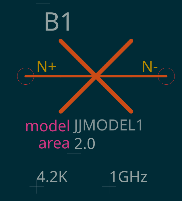
Josephson junctions can be used only with a connected Model element. The model carries every physical parameter used by the JSIM / JoSIM simulators; unspecified parameters fall back to each simulator's own default. To bind a model to a junction, write the model's name in the junction's MODEL attribute.
 |
 |
|---|---|
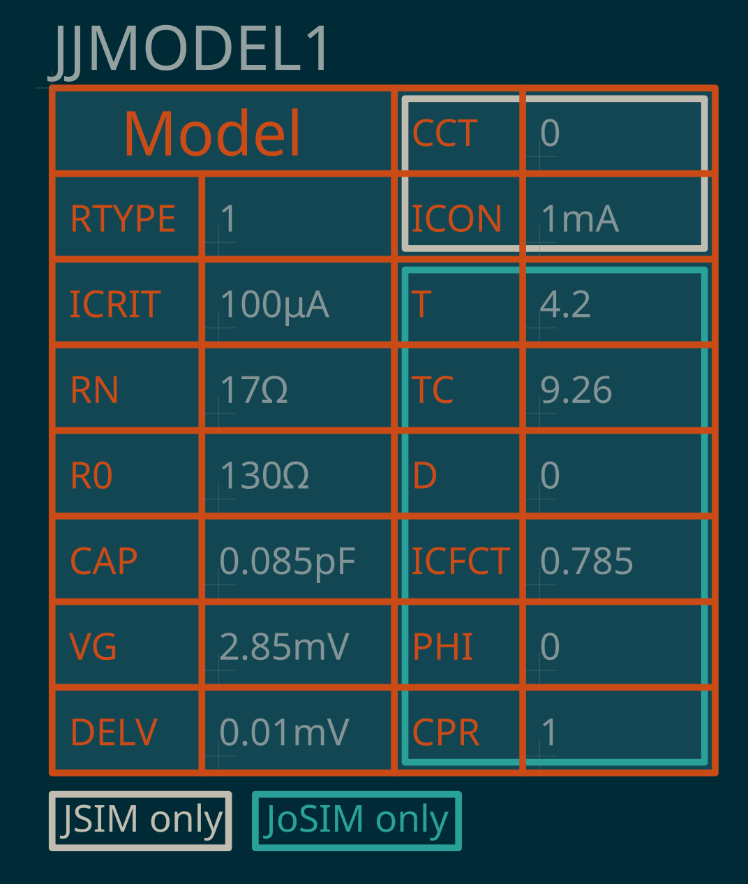
| B1 Josephson junction bound to model JJMODEL1. AREA=2.0 means that its critical current is 200 µA. JoSIM: thermal noise at 4.2K is considered over a bandwidth of 1 GHz. Alternatively, noise can be included through an additional noise source in the schematic or by JOINUS-D (works with JoSIM and JSIM) | Example JJMODEL1 .model parameters for junction B1 (default critical current: 100µA if AREA is not specified or AREA=1.0) |
2.5.1. Keyword attributes¶
Besides the model name, a few optional keyword attributes may be added directly on the junction's own line (e.g. B1 2 3 JJMOD1 AREA=1.5). Support differs between the two simulators:
| Attribute | JSIM | JoSIM | Description |
|---|---|---|---|
| MODEL | ✅ | ✅ | Name of the connected Model element. Required. |
| AREA | ✅ | ✅ | Junction-area multiplier. Scales ICRIT and CAP proportionally, and RN / R0 inversely, relative to the connected model. Default 1 (no scaling) on both simulators. |
| IC | ❌ | ✅ | Per-instance critical-current override. When set, JoSIM derives the effective area as AREA = IC / ICRIT_model, so IC and AREA express the same scaling — do not use both at once. |
| TEMP | ❌ | ✅ | Per-instance operating temperature (K), overriding the model's T for this junction only. |
| NEB | ❌ | ✅ | Per-instance noise-equivalent bandwidth (Hz) used by JoSIM's thermal-noise engine for this junction. Default 1 GHz. |
| CONDEV | ✅ | ❌ | Name of an inductor, voltage source or current source whose current modulates this junction's critical current. Takes effect only if the connected model sets CCT=1; see §2.5.2. |
| IC=V0,PHI0 | ✅ | ❌ | Initial voltage / phase conditions. Parsed by the JSIM syntax but currently ignored by the simulator. |
The Josephson Junction With Quasiparticles (BQP) accepts only MODEL, AREA and IC. It is not yet implemented in the tool-chain.
2.5.2. .MODEL parameters¶
The .MODEL block carries the junction's physical parameters. JSIM and JoSIM share most names, but their supported sets and built-in defaults are not identical — a parameter absent from a simulator's column is not recognised by it. The Library default column is the value pre-filled by the Superconductor library's Model component (a niobium process, Jc ≈ 10 kA/cm² = 100 µA/µm², nominal junction area ≈ 1 µm²).
| Parameter | JSIM default | JoSIM default | Library default | Units | Description |
|---|---|---|---|---|---|
| RTYPE | 0 | 1 | 1 | – | Subgap I-V linearisation. 0 = ideal (zero quasiparticle current below the gap); 1 = piece-wise-linear I-V curve. |
ICRIT (JoSIM alias IC) |
1 mA | 1 mA | 100 µA | – | Critical current of the junction. |
| RN | 5 | 5 | 17 | Ω | Normal-state (above-VG) resistance. |
| R0 | 30 | 30 | 130 | Ω | Subgap (below-VG) resistance. |
CAP (JoSIM alias C) |
2.5 pF | 2.5 pF | 0.085 pF | – | Junction capacitance. |
VG (JoSIM alias VGAP) |
2.8 mV | 2.8 mV | 2.85 mV | – | Gap voltage. |
| DELV | 0.1 mV | 0.1 mV | 0.01 mV | – | Width of the subgap-to-normal conductance transition. |
| CCT | 0 | ❌ | 0 | – | JSIM only. Control-current weighting for CONDEV modulation: 0 = none, 1 = sin(x)/x. |
| ICON | 1 mA | ❌ | 1 mA | – | JSIM only. Scale of the control current used by CONDEV modulation (must not be 0). |
| T | ❌ | 4.2 | 4.2 | K | JoSIM only. Junction operating temperature. |
| TC | ❌ | 9.1 | 9.26 | K | JoSIM only. Critical temperature of the superconductor. |
| D | ❌ | 0.0 | 0 | – | JoSIM only. Point-of-contact transparency (0–1), affecting the current-phase relationship. |
ICFCT (alias ICFACT) |
❌ | π/4 | 0.785 | – | JoSIM only. Ratio of critical current to the quasiparticle current-step height. |
| PHI | ❌ | 0 | 0 | rad (0–2π) | JoSIM only. Static phase offset, enabling φ-junction / π-junction behaviour. |
| CPR | ❌ | {1} | 1 | – | JoSIM only. Current-phase-relationship harmonic amplitudes, a single value or a {…} list. |
Critical-current modulation (JSIM only)
CONDEV=DEVNAME on the junction line names a device (inductor, voltage source or current source, referenced by name only) whose instantaneous current JSIM reads every timestep. It modulates the junction only when the connected model also sets CCT=1:
Icrit(t) = ICRIT × sinc( π · Icontrol(t) / ICON )
ICON is the control-current scale (first sinc lobe). With the default CCT=0, CONDEV is validated but has no effect.
Sources
JSIM parameters: JSIM User's Manual, §5.1. JoSIM parameters: JoSIM Syntax Guide.
2.6. SPICE Commands¶
Control commands are added from the SPICE Commands tab of LibrePCB.
Transient Analysis supplies the time-domain parameters. The library uses a single set of attribute names; each maps to a different position in the two simulators' .TRAN / .tran line:
| Library attribute | JSIM .TRAN |
JoSIM .tran |
|---|---|---|
| ANALYSIS | fixed TRANSIENT |
fixed |
| PSTEP | pos 1 — PRSTEP, print interval, mandatory | pos 4 — P_STEP, output print step, optional, must be ≥ the simulation step (SIMSTEP) |
| STOP | pos 2 — TSTOP, stop time, mandatory | pos 2 — T_STOP, end time, mandatory |
| PSTART | pos 3 — TSTART, output start time, optional (default 0) | pos 3 — P_START, output print start, optional |
| SIMSTEP | pos 4 — MAXTSTEP, max internal solver step, optional (default 1 ps) | pos 1 — T_STEP, internal simulation step, mandatory |
| PWINDOW | ❌ | pos 5 — P_WINDOW, Hanning FIR window width [s] for decimation, optional |
| DST | ❌ | pos 6 — DST, disable startup settling time (flag), optional |
Position 1 and position 4 are not the same thing in both simulators
The .TRAN / .tran command is not simply a case of one simulator supporting a subset of the other's parameters at matching positions — the two disagree on what a given position means:
- Position 1 is the output print interval for JSIM, but the internal simulation step for JoSIM.
- Position 4 is the mirror image: the internal step for JSIM, the output print step for JoSIM.
A line written for one simulator cannot be reused as-is for the other by filtering or reordering — the values must be remapped to the position carrying the equivalent meaning. JOINUS-D and L2SPICE do this automatically.
Automatic .TRAN when the schematic has none
Both JSIM and JoSIM refuse to run without a .TRAN line. If a schematic has no Transient Analysis component, JOINUS-D still produces a runnable netlist:
- it inserts a default
.TRANline with a#WARNING!comment just above it; - the default values are PSTART 0 ps, PSTEP 1 ps, STOP 150 ps, SIMSTEP 0.5 ps, changeable under Preferences → Miscellaneous → "Default transient analysis (.TRAN)";
- on back-annotation, JOINUS-D turns the injected line into a real Transient Analysis component copied from your installed Superconductor library and placed near the top-left of the first sheet. (If the library is not installed, back-annotation stops and asks you to install it.)
Once a Transient Analysis component exists, its values always win.
JSIM only — automatic STOP and PULSE-period corrections
JSIM (not JoSIM) crashes, or refuses to start, on some otherwise-legal PULSE sources. On a JSIM conversion, JOINUS-D checks every Current Pulse and Voltage Pulse source and repairs the netlist only — the schematic is never changed — adding a #WARNING! line for every change:
| Problem | JSIM without the guard | What JOINUS-D does |
|---|---|---|
| the run ends during a pulse's rise or fall | crash (breakpoint-tree stack overflow) | raises STOP to the smallest value that ends while every pulse is in its flat off state, rounded up to 5 ps; TD / TR / TF / PW / PER are left untouched |
PER is empty |
"illegal pulse source definition", job aborted | fills PER with a value just past STOP, so the pulse fires exactly once — as JoSIM does automatically |
PER < TR + TF + PW |
crash | cannot be fixed through STOP — a #WARNING! asks you to lengthen the period |
Because Phase Pulse sources are JoSIM-only, on a JSIM conversion they are removed (with an *ERROR! comment) before this check.
.PARAM (New in v0.3, JoSIM only.) places named equations in the netlist. Example: .param Rshunt=IcRs/ICRIT together with Rs 20 10 Rshunt sizes Rs so that the desired Rs·Ic product (McCumber parameter) is met. Two slots — EQUATION1, EQUATION2 — per component; add more .PARAM components for more equations. On a JSIM conversion the block is dropped with an *ERROR! comment.
Comments passes up to five free-text lines (LINE1 … LINE5) into the netlist, placed just after the header on both simulators.
2.7. Measurement devices¶
To observe simulation results, output parameters must be defined explicitly. The following elements produce that output:
- Ammeter — current between N+ and N−; place it in parallel with the branch being sensed (unlike a real ammeter).
- Voltmeter — voltage between N+ and N−.
- Phasemeter — phase difference between N+ and N−.
- Voltage probe — voltage of one node with respect to ground.
- Phase probe — phase of one node with respect to ground. JoSIM only.
Since v0.3 every measurement device has a LEGEND field: a custom label read and displayed by FrugalPlot. A FILENAME field routes the device's .PRINT output to a file (empty ⇒ console); it is only needed when JSIM / JoSIM are run standalone, as JOINUS-D and L2SPICE manage output files themselves.
The Ammeter's CURRENT_MODE attribute (JSIM only) selects which junction-current contribution is printed: JJTOTAL, JJJOSEPH, JJCAP, JJRESIS or JJALL (see the JSIM manual §7.4). Leave empty for an ordinary device current.
Measurement devices and subcircuits
Ammeters, voltmeters and probes placed in a circuit that is later converted into a subcircuit are dropped: their internal nodes become local to the subcircuit and are no longer reachable from the parent. To observe a signal inside a subcircuit instance, use a Subcircuit Multimeter in the main circuit (§2.7.1).
2.7.1. Subcircuit Multimeter¶
New in v0.3. The Subcircuit Multimeter (default value {{MULTIMETER}}, prefix XPROBE) is a pinless annotation component — like Transient Analysis or Comments — that can be dropped anywhere on the main schematic. It emits .PRINT statements reaching devices and nodes inside a subcircuit instance, which ordinary meters and probes cannot access. A Subcircuit Multimeter belonging to a circuit that is itself converted into a subcircuit is ignored.
Its attributes are numbered slot pairs — PRINT1 / LEGEND1, PRINT2 / LEGEND2, … — plus one component-wide FILENAME that routes every slot to a file. Order does not matter. Each non-empty PRINT<n> starts with a type keyword and produces one .PRINT line; the matching LEGEND<n> is an optional FrugalPlot label.
| PRINT<n> value | Prints |
|---|---|
DEVI path [mode]DEVI L3|XDCSFQinDEVI B3|XDCSFQin JJRESIS |
Current through a device inside a subcircuit instance. mode (JSIM only, ignored by JoSIM) picks the junction-current component — JJTOTAL / JJJOSEPH / JJCAP / JJRESIS / JJALL, see §2.7. |
DEVV pathDEVV L3|XDCSFQin |
Voltage across a device inside a subcircuit instance. |
PHASE pathPHASE B3|XDCSFQin |
Phase across a device inside a subcircuit instance. JoSIM: any two-terminal device; JSIM: junctions only. |
NODEV node [node]NODEV 70|XDCSFQinNODEV 70|XDCSFQin 60|XDCSFQin |
Voltage of one subcircuit-internal node (w.r.t. ground) or between two of them. Qualify every node as <node>|<Xinstance>. |
NODEP node [node]NODEP 70|XDCSFQin 60|XDCSFQin |
Phase, same rules as NODEV. JoSIM only. |
anything elseVout → #WARNING! |
A #WARNING! comment, no .PRINT line. |
path is a hierarchical device path. Write it in any of three equivalent spellings — L0|XDCSFQin (JoSIM pipe), L0.XDCSFQin (JoSIM dot) or XDCSFQin_L0 (JSIM underscore); L2SPICE rewrites it into the target simulator's own form. The path may nest to any depth: B3|XJTL2|XTOP reaches junction B3 in instance XJTL2 inside instance XTOP.
node is an internal node given by its number with the same instance suffix, e.g. 70|XDCSFQin. Schematic net names are resolved only against the main circuit, so a subcircuit-internal node cannot be named — use its number.
Each token is resolved on its own: an unqualified token against the main circuit, a <node>|<Xinstance> token against that instance. A qualified and an unqualified token can be mixed — NODEP 40 70|XDCSFQin gives the phase between main-circuit node 40 and internal node 70 — but only if every token exists. NODEP 70 60|XDCSFQin therefore works only when the main circuit also has a node 70; if it does not, 70 resolves to nothing and the whole line is dropped. To read an internal node, qualify it: NODEP 70|XDCSFQin 60|XDCSFQin.
Simulator support. DEVI and DEVV work on both simulators. PHASE on a non-junction, and every NODEP form, are JoSIM only — on a JSIM conversion JOINUS-D and L2SPICE comment the line out (* … /* JSIM: node phase (NODEP) not supported — line disabled */). JSIM has no hierarchical node addressing at all; for a design that must also run on JSIM, expose the node as a .SUBCKT port and read it with an ordinary Voltage or Phase Probe.
Round-trip: LEGEND<n> and FILENAME are updated in both directions. PRINT<n> is back-annotated only for the DEVI / DEVV / PHASE forms (restored in canonical JoSIM pipe spelling); the NODEV / NODEP forms are not.
NODEV / NODEP on main-circuit nodes
NODEV and NODEP also read main-circuit nodes, where each token may be a raw node number or a schematic net name (resolved automatically). One node is measured with respect to ground.
| PRINT<n> value | Prints |
|---|---|
NODEV in out |
voltage between nets in and out |
NODEV clk |
voltage of net clk with respect to ground |
NODEP 40 20 |
phase between nodes 40 and 20 (JoSIM only) |
NODEP is JoSIM-only, like the stand-alone Phase Probe; NODEV works on both simulators. Neither is back-annotated — the net-name-to-number resolution cannot be reversed.
2.8. Subcircuits¶
Subcircuits encapsulate a portion of a schematic into a single modular component, enabling hierarchical design and reuse. To use a subcircuit it must first be named and saved in its SPICE-compatible form with L2SPICE. and JOINUS-D.
- JSIM: port nodes are integers only;
0is ground. - JoSIM: port nodes can be alphanumeric names or integers;
0andGNDare ground.
Subcircuits are auto-included recursively by JOINUS-D and L2SPICE when the referenced file is found. Standalone JSIM requires the .SUBCKT blocks to be pasted into the main netlist by hand; standalone JoSIM can use .INCLUDE.
2.9. InductEx¶
New in v0.3. The Port component marks connection points for circuits processed with InductEx. Not implemented yet in JOINUS-D.
3. Conventions & references¶
Sign conventions.
- The voltage (VN+ – VN−) is positive by convention for all voltage sources.
- The phase difference (φN+ – φN−) is positive by convention for all phase sources.
- The current flowing from N+ to N− inside any current source is positive by convention.
- The current flowing from NC+ to NC− inside any dependent source is positive by convention.
Phase values are entered as plain dimensionless numbers, in radians. JoSIM applies no unit scaling to the phase-source amplitude attributes (PHASE, PHASE0, PHASE1, …), unlike the AC sources' optional degrees-valued phase-shift argument. Because LibrePCB has no radian unit, these attributes are typed as plain text (no unit shown), exactly like the T0/T1/… time attributes.
Parameter references. The full parameter set of each component is documented in the simulators' own references:
- JoSIM Syntax Guide for JoSIM;
- the original JSIM manual for JSIM; noise-element syntax is in Appendix B.
Reserved attributes
Some attributes of certain components are not used by the simulators. They are reserved for future FrugalEDA functionality.
Part II — Component reference¶
4. Josephson Junctions¶
| Component Name | Prefix | Symbol | Comments |
|---|---|---|---|
| Josephson Junction |
B |
 |
Pins N+, N−. Requires a connected Model (MODEL attribute). Keyword attributes: AREA, CONDEV (JSIM), IC, TEMP, NEB (JoSIM) — see §2.5.1. RTYPE=0 is the JSIM default, RTYPE=1 the JoSIM default. |
| Josephson Junction With Quasiparticles |
BQP |
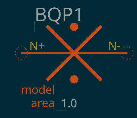 |
Pins N+, N−. Attributes MODEL, AREA, IC. Adds the full quasiparticle electrodynamics. Not yet implemented in the tool-chain. |
| Model |
JJMODEL |
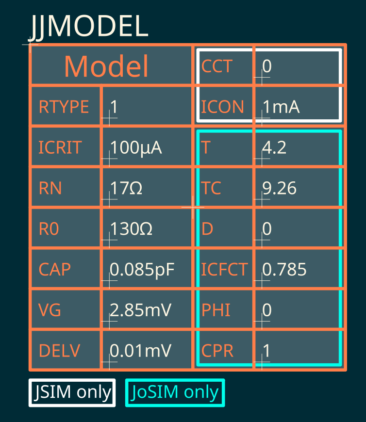 |
Pinless .model block. Attributes: RTYPE, ICRIT, RN, R0, CAP, VG, DELV, plus CCT, ICON (JSIM only) and T, TC, D, ICFCT, PHI, CPR (JoSIM only). Defaults per §2.5.2. |
5. Signal Sources¶
5.1. Waveform reference (all signal sources)¶
The tables below use the generic amplitude symbol A. Substitute the concrete attribute name of the family:
| Family | Prefix pattern | Amplitude attributes | Amplitude type in LibrePCB |
|---|---|---|---|
| Current | I… |
I, I0, I1, I2 |
current (A) |
| Voltage | V… |
V, V0, V1, V2 |
voltage (V) |
| Phase | PH… |
PHASE, PHASE0, PHASE1, PHASE2 |
plain text, radians |
Time attributes (T0, T1, TD, TR, …) are always plain text and accept SPICE unit suffixes (ps, ns, …).
5.1.1. DC¶
Constant amplitude held for the whole run. JoSIM syntax: DC A.
Examples: I1 0 20 DC 100u, V1 40 0 DC 2m, PH1 40 0 DC pi
JSIM has no DC source: L2SPICE emits an equivalent 2-point PWL. Phase DC is JoSIM-only.
5.1.2. AC¶
(phase: JoSIM only)
A(t) = A0 + A·sin(2π·FREQ·(t − TD))·e−THETA·(t − TD)
Keyword SIN(A0 A FREQ TD THETA). JSIM requires all five arguments; JoSIM needs only the first three.
Examples: ISIN1 1 0 SIN(0 100u 100G 0 0), VSIN1 1 0 SIN(0 2m 100G 0 0), PHSIN1 1 0 SIN(0 3.14 100G) (phase: JoSIM only)
| Attribute | JSIM | JoSIM | Description |
|---|---|---|---|
| A0 | ✅ (must be 0) | ✅ | DC offset. Non-zero values are forced to 0 for JSIM during conversion. |
| A | ✅ | ✅ | Sinusoid amplitude. |
| FREQ | ✅ | ✅ | Frequency. Defaults to 1 / STOP (one period). |
| TD | ✅ | ✅ | Start delay. |
| THETA | ✅ | ✅ | Damping factor (inverse time). For a decaying envelope it must be negative in JSIM (sign bug in the simulator) and positive in JoSIM. |
5.1.3. PWL — Piece-Wise Linear¶
(phase: JoSIM only)
PWL(0 0 T0 A0 T1 A1 … TN AN) — straight-line interpolation between breakpoints.
Examples: IPWL1 1 0 PWL(0 0 5p 100u 10p 0), VPWL1 1 0 PWL(0 0 5p 1m 10p 0), PHPWL1 1 0 PWL(0 0 5p 6.283) (phase: JoSIM only)
| Attribute | JSIM | JoSIM | Description |
|---|---|---|---|
| T0, A0 | ✅ | ✅ | First breakpoint. Both must be 0. |
| T1, A1, … | ✅ | ✅ | Further breakpoints. Add attribute pairs T2/A2, T3/A3, … in LibrePCB for more segments. Times must strictly increase. |
5.1.4. PWS — Piece-Wise Sinusoidal¶
New in v0.3. JoSIM only. PWS(0 0 T0 A0 T1 A1 … TN AN) — like PWL, but each segment is a half-cosine curve instead of a straight line. Same attributes as PWL. On a JSIM conversion the source is removed with an *ERROR! comment.
Examples: IPWS1 1 0 PWS(0 0 5p 100u 10p 0), VPWS1 1 0 PWS(0 0 5p 1m 10p 0), PHPWS1 1 0 PWS(0 0 5p 6.283)
5.1.5. Pulse¶
(phase: JoSIM only)
Keyword PULSE(A1 A2 TD TR TF PW PER).
Examples: IPULSE1 1 0 PULSE(0 100u 0 2p 2p 10p 100p), VPULSE1 1 0 PULSE(0 1m 0 2p 2p 10p 100p), PHPULSE1 1 0 PULSE(0 6.283 0 2p 2p 10p 100p) (phase: JoSIM only)
| Attribute | JSIM | JoSIM | Description |
|---|---|---|---|
| A1 | ✅ (must be 0) | ✅ | Base amplitude before the pulse. Non-zero values are forced to 0 for JSIM. |
| A2 | ✅ | ✅ | Pulse-top amplitude (A2 − A1 is the pulse height). |
| TD | ✅ | ✅ | Start delay. |
| TR | ✅ | ✅ | Rise time. JoSIM default: SIMSTEP. |
| TF | ✅ | ✅ | Fall time. JoSIM default: SIMSTEP. |
| PW | ✅ | ✅ | Pulse width (excluding rise/fall). JoSIM default: STOP. |
| PER | ✅ (required, > TR+TF+PW) | ✅ | Repetition period. JoSIM default: STOP (single pulse). For JSIM, JOINUS-D and L2SPICE fill an empty PER and repair a STOP landing on a pulse edge — see the warning in §2.6. |
5.1.6. Noise¶
(phase: JoSIM only)
Example: VNOISE1 10 0 NOISE(10n 10ps 1ps)
A(t) = A·GRAND() / √(2·Δt), with GRAND() a unit-variance Gaussian generator and Δt the time step over which the sample is held.
- JoSIM uses TSTEP as Δt, so the amplitude is A / √(2·TSTEP).
- JSIM (
jsim_n, Satchell stochastic extension — current and voltage only) uses its own solver step for Δt and merely forces that step to stay ≤ TSTEP. Where the solver runs faster than TSTEP the instantaneous amplitude is correspondingly larger.
| Attribute | JSIM | JoSIM | Description |
|---|---|---|---|
| A | ✅ | ✅ | Spectral amplitude density (V/√Hz, A/√Hz or rad/√Hz). |
| TD | ✅ | ✅ | Delay before the noise starts. |
| TSTEP | ✅ | ✅ | Noise time step: sets the effective noise bandwidth (≈ 1 / 2·TSTEP) and bounds the stochastic-algorithm error. It is a per-source attribute, independent of the .TRAN SIMSTEP (§2.6). In JoSIM the bandwidth may also be set with .neb (global) or neb= (per-resistor); JSIM has no such command and instead injects resistor thermal noise through the noise.awkf script. Alternatively JOINUS-D can directly inject resistor thermal noise for both simulators. |
Phase Noise is JoSIM-only.
5.1.7. Relaxation¶
JoSIM only (EXP source). Keyword EXP(A1 A2 TD1 TAU1 TD2 TAU2).
Examples: IRELAX1 1 0 EXP(0 100u 5p 1p 15p 1p), VRELAX1 1 0 EXP(0 1m 5p 1p 15p 1p), PHRELAX1 1 0 EXP(0 6.283 5p 1p 15p 1p)
Three segments:
- t < TD1: A(t) = A1
- TD1 ≤ t < TD2: A(t) = A1 + (A2 − A1)·(1 − e−(t−TD1)/TAU1)
- t ≥ TD2: the above plus (A1 − A2)·(1 − e−(t−TD2)/TAU2)
| Attribute | JSIM | JoSIM | Description |
|---|---|---|---|
| A1 | ❌ | ✅ | Initial / final plateau amplitude. (Phase family: attribute PHASE1.) |
| A2 | ❌ | ✅ | Peak amplitude. (Phase family: PHASE2.) |
| TD1 | ❌ | ✅ | Rise start. JoSIM default 0. |
| TAU1 | ❌ | ✅ | Rise time constant. JoSIM default TD1 + SIMSTEP. |
| TD2 | ❌ | ✅ | Decay start. JoSIM default SIMSTEP. |
| TAU2 | ❌ | ✅ | Decay time constant. JoSIM default SIMSTEP. |
5.1.8. Custom Waveform¶
JoSIM only (CUS source). Samples are read from a plain-text file holding one line of space-separated amplitudes (e.g. 0 2 3 6 2 1 0). Keyword CUS(FILENAME TS SF IM TD PER).
Examples: ICUSTOM1 1 0 CUS(wave.txt 1p 1 1), VCUSTOM1 1 0 CUS(wave.txt 1p 1 1), PHCUSTOM1 1 0 CUS(wave.txt 1p 1 1)
| Attribute | JSIM | JoSIM | Description |
|---|---|---|---|
| FILENAME | ❌ | ✅ | Wave file. Default input.txt. The symbol displays the file name. |
| TS | ❌ | ✅ | Time step between successive samples. |
| SF | ❌ | ✅ | Scale factor applied to every sample. |
| IM | ❌ | ✅ | Interpolation between samples: 0 = none, 1 = linear, 2 = cubic. |
| TD | ❌ | ✅ | Delay before the waveform starts. |
| PER | ❌ | ✅ | 1 = repeat the pattern for the whole run; empty / 0 = play once. |
5.2. Current Sources¶
| Component Name | Prefix | Symbol | Comments |
|---|---|---|---|
| Current DC |
I |
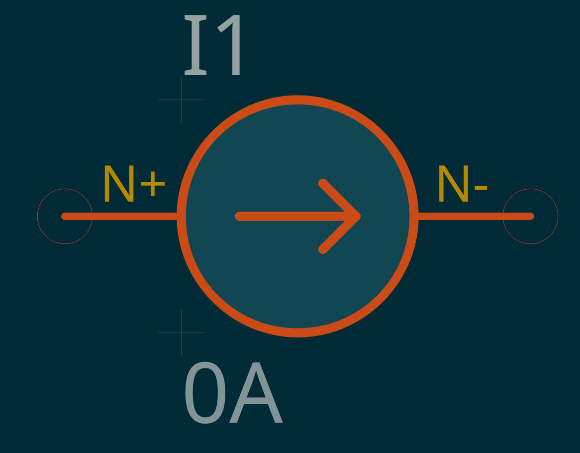 |
Attribute I. Converted to an IPWL source for JSIM during L2SPICE conversion. |
| Current AC |
ISIN |
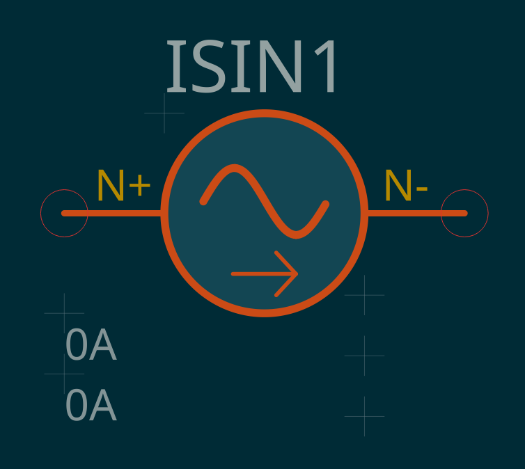 |
Attributes I0, I, FREQ, TD, THETA. See §5.1.2 · AC. |
| Current PWL |
IPWL |
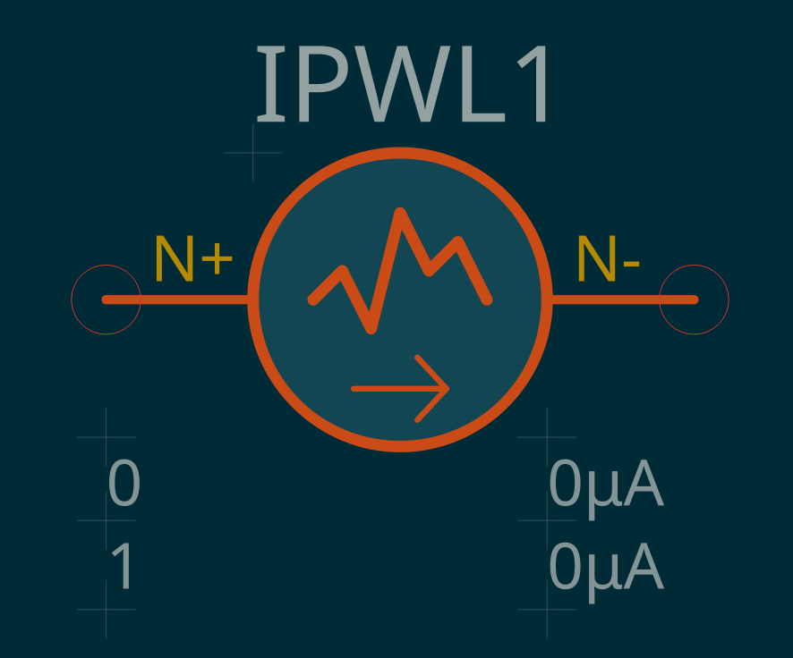 |
Attributes T0/I0 (must be 0), T1/I1, … PWL(0 0 T0 I0 … TN IN). |
| Current PWS |
IPWS |
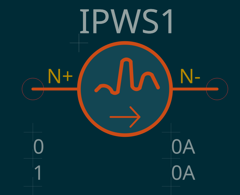 |
New in v0.3, JoSIM only. Same attributes as IPWL; half-cosine interpolation. |
| Current Pulse |
IPULSE |
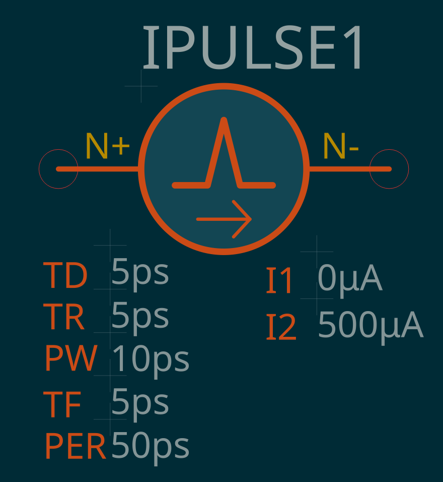 |
Attributes I1 (0 for JSIM), I2, TD, TR, TF, PW, PER. For JSIM the period is auto-repaired — see §2.6. |
| Current Noise |
INOISE |
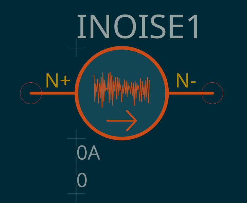 |
Attributes I, TD, TSTEP. |
| Current Relaxation |
IRELAX |
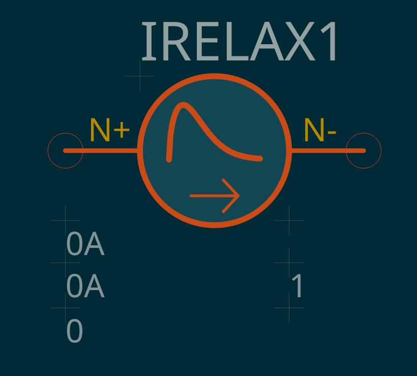 |
JoSIM only. Attributes I1, I2, TD1, TAU1, TD2, TAU2. |
| Current Custom Waveform |
ICUSTOM |
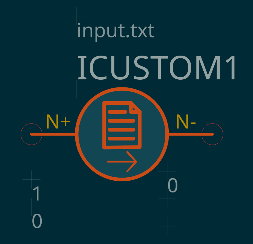 |
JoSIM only. Attributes FILENAME (input.txt), TS, SF, IM, TD, PER. |
5.3. Voltage Sources¶
| Component Name | Prefix | Symbol | Comments |
|---|---|---|---|
| Voltage DC |
V |
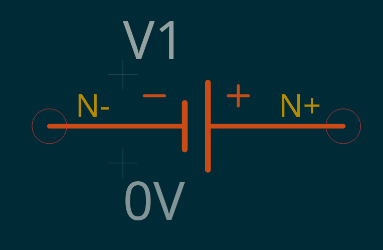 |
Attribute V. Converted to a VPWL source for JSIM during L2SPICE conversion. |
| Voltage AC |
VSIN |
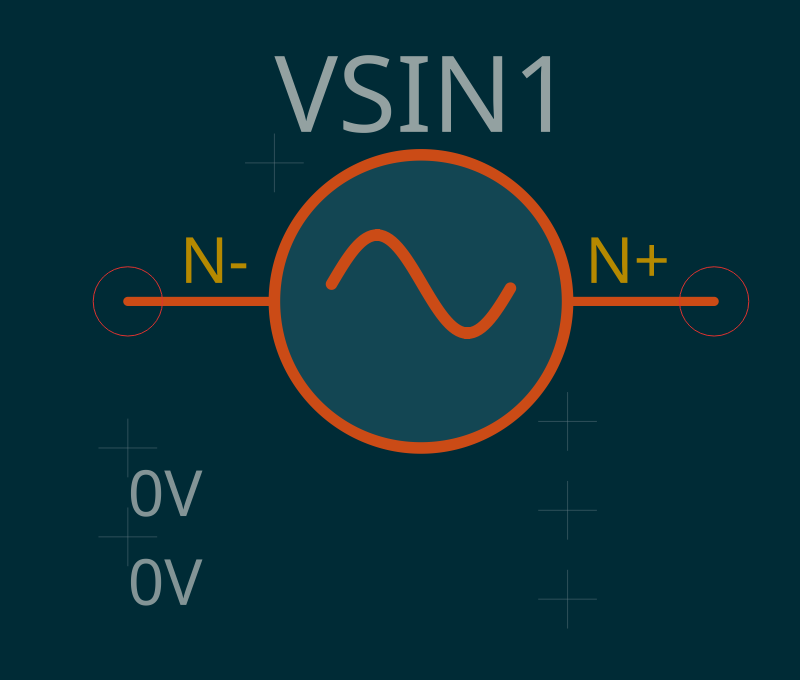 |
Attributes V0, V, FREQ, TD, THETA. See §5.1.2 · AC. |
| Voltage PWL |
VPWL |
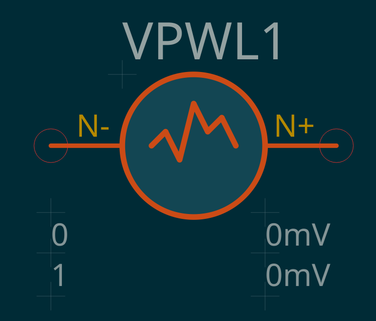 |
Attributes T0/V0 (must be 0), T1/V1, … PWL(0 0 T0 V0 … TN VN). |
| Voltage PWS |
VPWS |
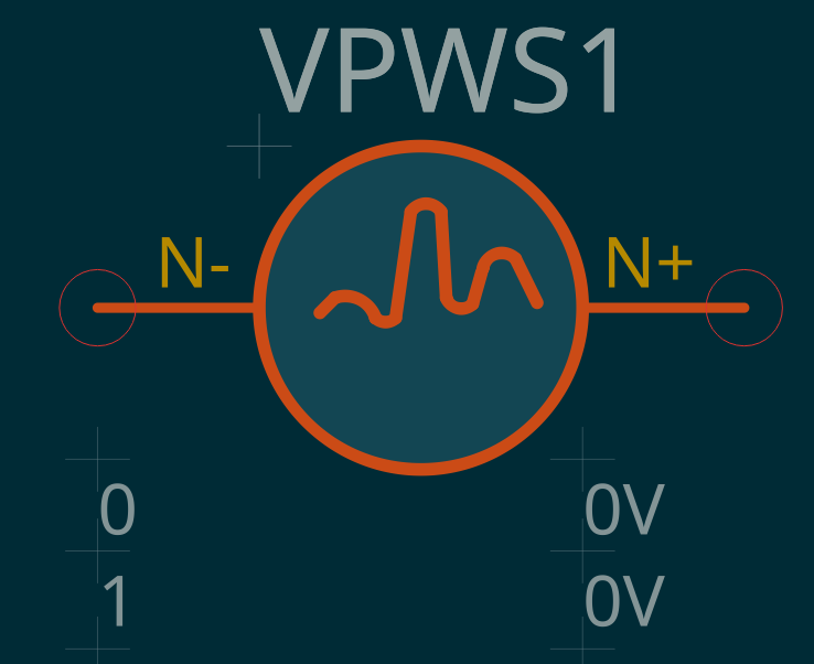 |
New in v0.3, JoSIM only. Same attributes as VPWL; half-cosine interpolation. |
| Voltage Pulse |
VPULSE |
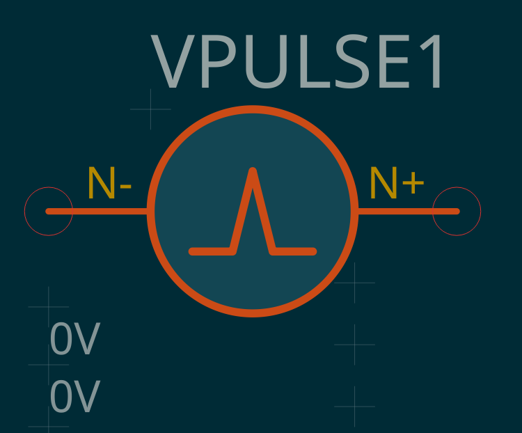 |
Attributes V1 (0 for JSIM), V2, TD, TR, TF, PW, PER. For JSIM the period is auto-repaired — see §2.6. |
| Voltage Noise |
VNOISE |
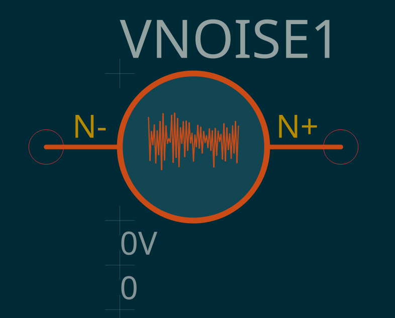 |
Attributes V, TD, TSTEP. |
| Voltage Relaxation |
VRELAX |
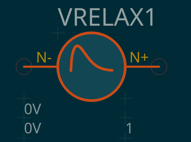 |
JoSIM only. Attributes V1, V2, TD1, TAU1, TD2, TAU2. |
| Voltage Custom Waveform |
VCUSTOM |
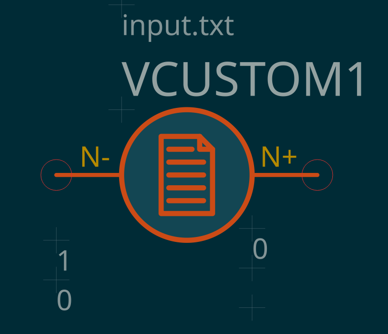 |
JoSIM only. Attributes FILENAME (input.txt), TS, SF, IM, TD, PER. The symbol displays the source file name. |
5.4. Phase Sources¶
Supported by JoSIM only. On a JSIM conversion every phase source is removed with an *ERROR! comment. Amplitude attributes are plain-text radians.
| Component Name | Prefix | Symbol | Comments |
|---|---|---|---|
| Phase DC |
PH |
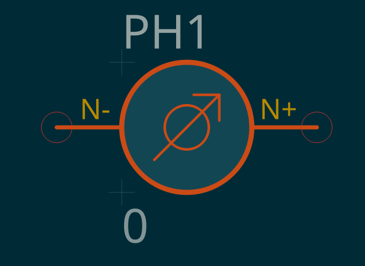 |
Attribute PHASE. |
| Phase AC |
PHSIN |
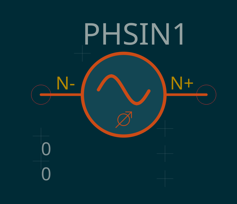 |
Attributes PHASE0, PHASE, FREQ, TD, THETA. |
| Phase PWL |
PHPWL |
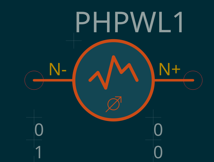 |
Attributes T0/PHASE0 (must be 0), T1/PHASE1, … PWL(0 0 T0 Φ0 … TN ΦN). |
| Phase PWS |
PHPWS |
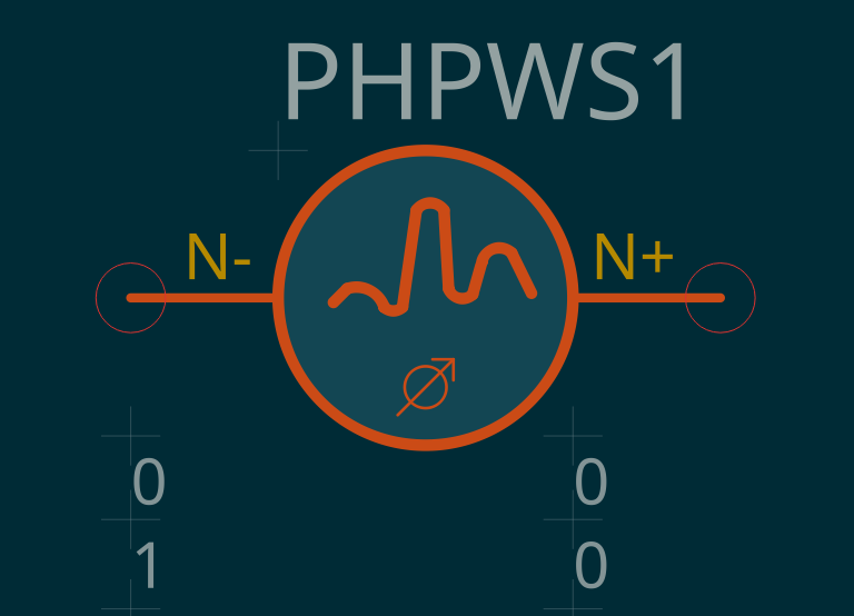 |
New in v0.3. Same attributes as PHPWL; half-cosine interpolation. |
| Phase Pulse |
PHPULSE |
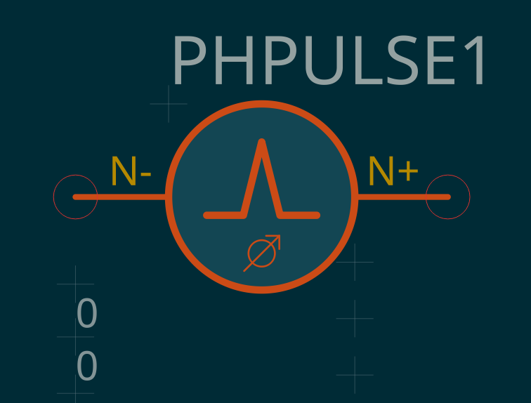 |
Attributes PHASE1, PHASE2, TD, TR, TF, PW, PER. |
| Phase Noise |
PHNOISE |
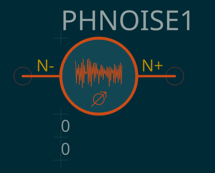 |
Attributes PHASE, TD, TSTEP. |
| Phase Relaxation |
PHRELAX |
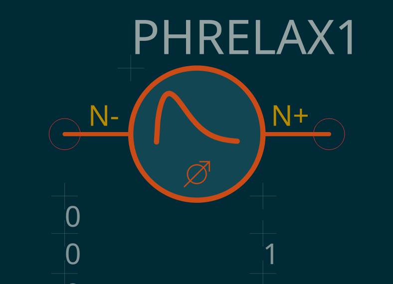 |
Attributes PHASE1, PHASE2, TD1, TAU1, TD2, TAU2. |
| Phase Custom Waveform |
PHCUSTOM |
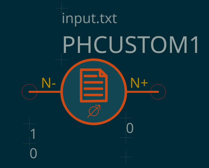 |
Attributes FILENAME (input.txt), TS, SF, IM, TD, PER. |
6. Dependent Signal Sources¶
New in v0.3. JoSIM only — on a JSIM conversion these are dropped with an *ERROR! comment. Pins: output N+ / N−, control NC+ / NC−. See §2.4.
| Component Name | Prefix | Symbol | Comments |
|---|---|---|---|
| Voltage-Controlled Voltage Source |
E |
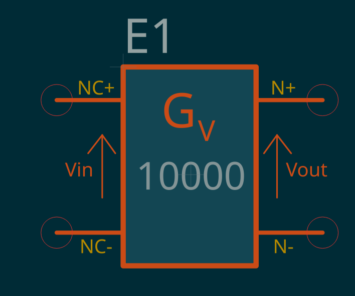 |
Attribute G_V (voltage gain, V/V, default 1). V(N+,N−) = G_V · V(NC+,NC−). |
| Current-Controlled Current Source |
F |
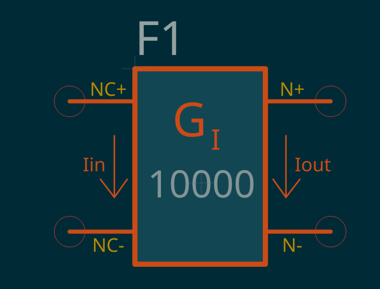 |
Attribute G_I (current gain, A/A, default 1). I(N+→N−) = G_I · I(NC+,NC−). |
| Voltage-Controlled Current Source |
G |
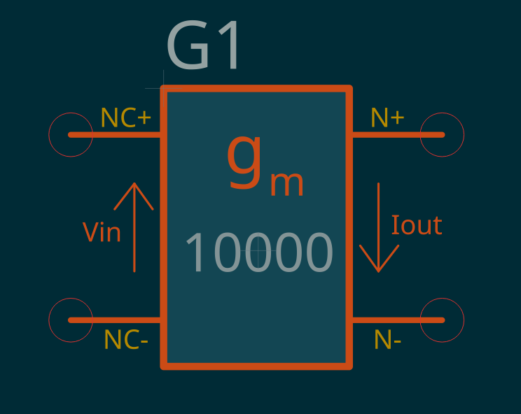 |
Attribute G_M (transconductance, S, default 1). I(N+→N−) = G_M · V(NC+,NC−). |
| Current-Controlled Voltage Source |
H |
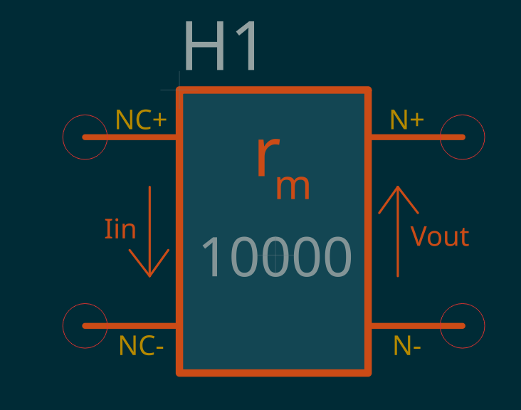 |
Attribute R_M (transresistance, Ω, default 1). V(N+,N−) = R_M · I(NC+,NC−). |
7. Measurement Devices¶
| Component Name | Prefix | Symbol | Comments |
|---|---|---|---|
| Ammeter |
CURR |
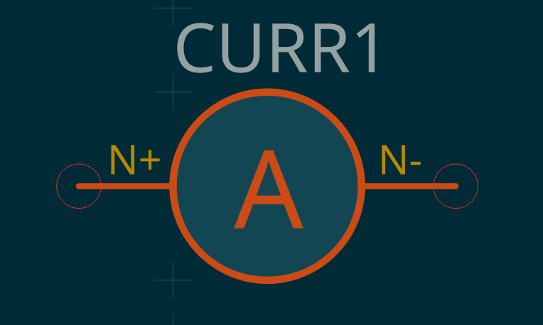 |
Pins N+, N−. Place in parallel with the sensed branch. Attributes PRINT_TYPE=DEVI (fixed), DEVICE_NAME, FILENAME, LEGEND, CURRENT_MODE (JSIM only: JJTOTAL/JJJOSEPH/JJCAP/JJRESIS/JJALL). |
| Voltmeter |
VOLT |
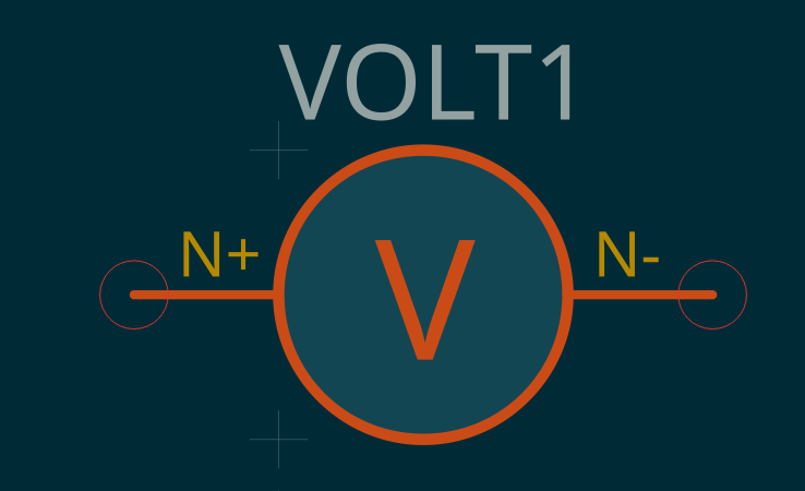 |
Pins N+, N−. Attributes PRINT_TYPE=DEVV (fixed), DEVICE_NAME, FILENAME, LEGEND. |
| Phasemeter |
PHASE |
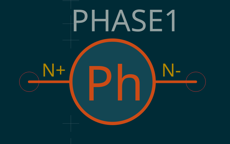 |
Pins N+, N−. Attributes PRINT_TYPE=PHASE (fixed), DEVICE_NAME, FILENAME, LEGEND. |
| Voltage Probe |
VPROBE |
 |
One pin. Measures node voltage w.r.t. ground. Attributes PRINT_TYPE=NODEV (fixed), FILENAME, LEGEND. |
| Phase Probe |
PHPROBE |
 |
JoSIM only. One pin. Measures node phase w.r.t. ground. Attributes PRINT_TYPE=NODEP (fixed), FILENAME, LEGEND. |
| Subcircuit Multimeter |
XPROBE |
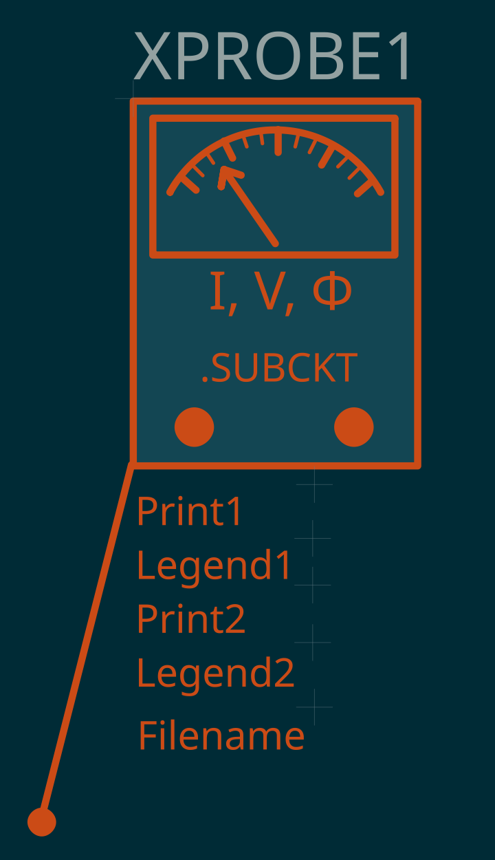 |
New in v0.3. Pinless. Numbered PRINT<n> / LEGEND<n> slots plus one FILENAME. Reaches devices and nodes inside a subcircuit instance — see §2.7.1. |
8. Passive Components¶
| Component Name | Prefix | Symbol | Comments |
|---|---|---|---|
| Capacitor |
C |
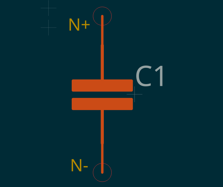 |
Pins N+, N−. Attribute CAPACITANCE. |
| Resistor |
R |
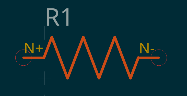 |
Pins N+, N−. Attribute RESISTANCE, plus TEMP and NEB (JoSIM only — physical temperature and thermal-noise bandwidth, default 1 GHz). |
| Inductor |
L |
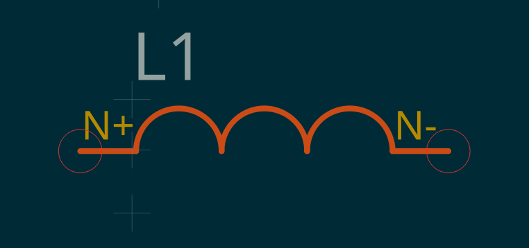 |
Pins N+, N−. Attribute INDUCTANCE, plus FCHECK (JSIM only flag — track flux changes; use on one inductor per superconducting loop) and FVALUE (JSIM only — per-inductor multiplier on the global MAXFLUXSTEP, default 1; only meaningful with FCHECK). |
| Mutual Inductor |
K |
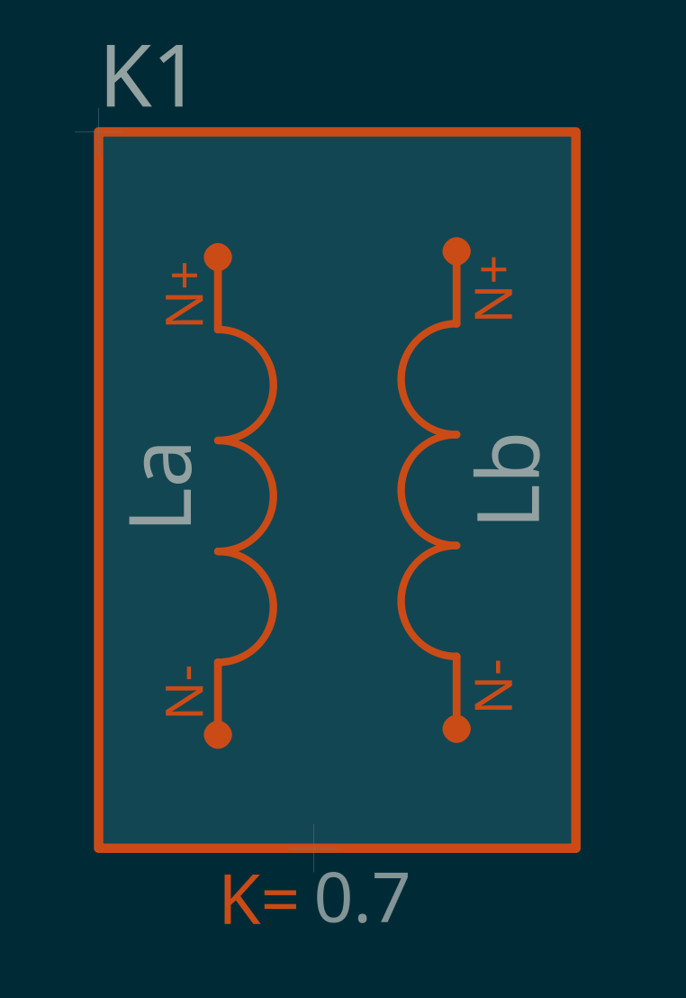 |
Pinless — place as an unconnected block. Attributes L1, L2 (the names of the two coupled inductors) and K (coupling factor, 0 ≤ K ≤ 1). M = K·√(L1·L2). Both inductors must exist in the circuit. |
9. SPICE commands¶
| Component Name | Prefix | Symbol | Comments |
|---|---|---|---|
| Transient Analysis |
TRAN |
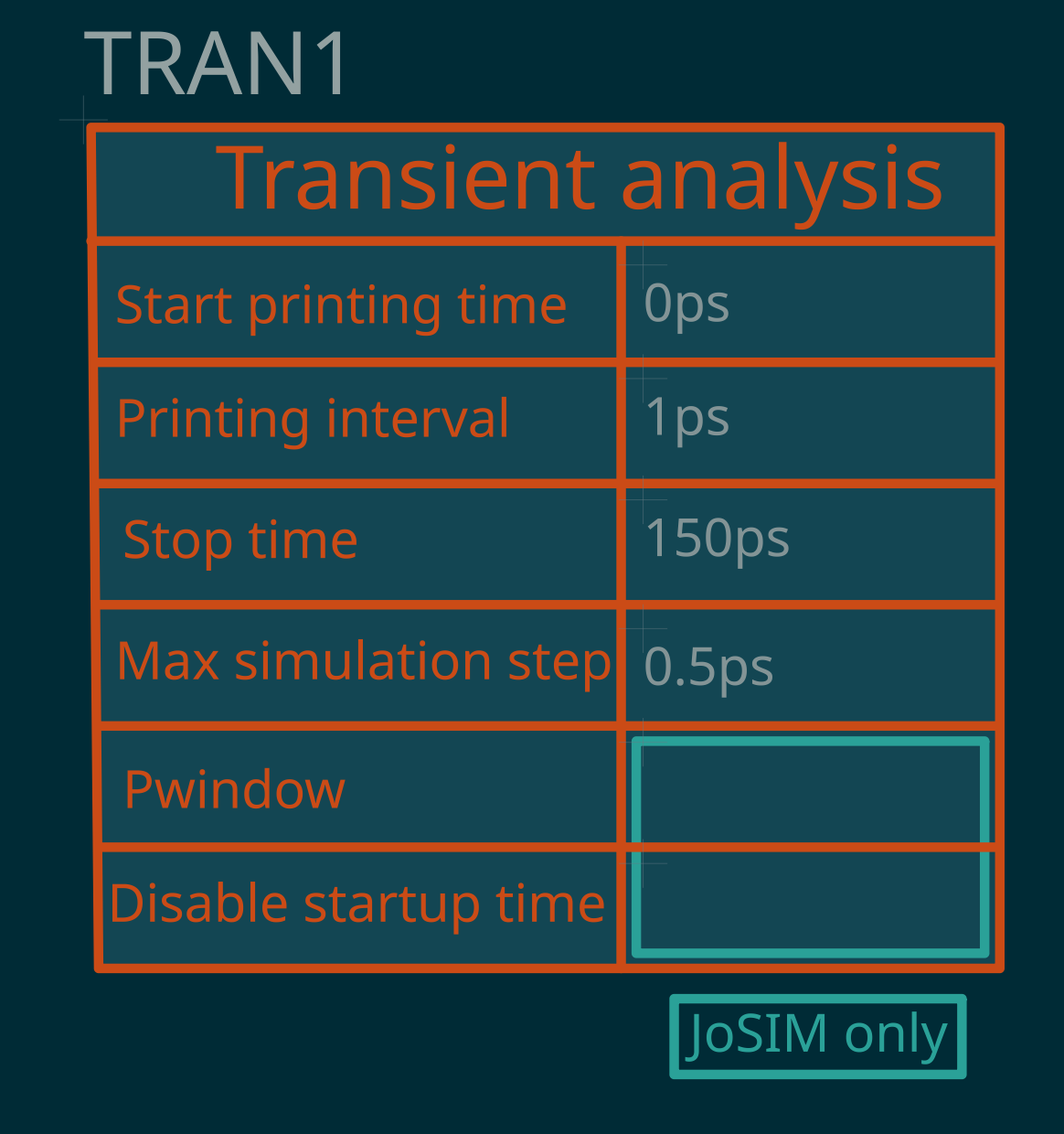 |
Pinless. Attributes ANALYSIS (TRANSIENT), PSTART, PSTEP, STOP, SIMSTEP, plus PWINDOW and DST (JoSIM only). Position mapping in §2.6. |
.PARAM |
PARAM |
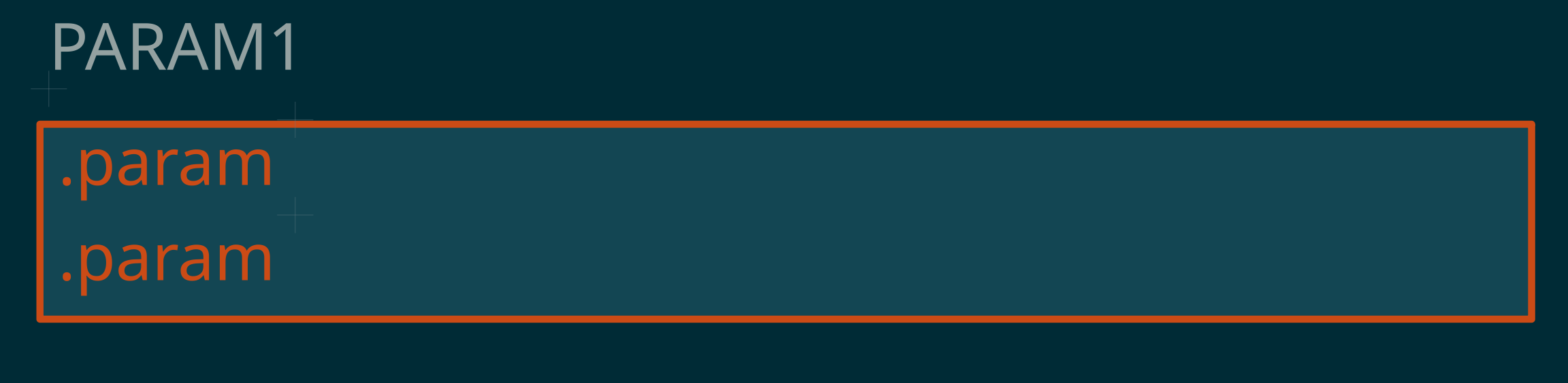 |
New in v0.3, JoSIM only. Pinless. Attributes EQUATION1, EQUATION2 — named equations placed in the netlist (e.g. Rshunt=IcRs/ICRIT). Add more .PARAM components for more equations. |
| Comments |
Comments |
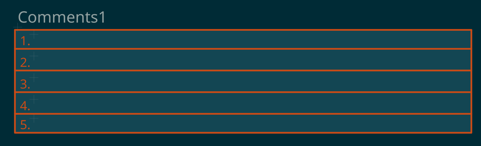 |
Pinless. Attributes LINE1 … LINE5 — free text placed just after the netlist header. |
10. Subcircuits¶
All variants share the prefix SUBC, the attribute SUBCIRCUIT_NAME, and numbered port pins 1, 2, … Ports 1–4 are required; the 6- and 8-port variants have optional ports. See §2.8.
| Component Name | Prefix | Symbol | Comments |
|---|---|---|---|
| Subcircuit 1 port |
SUBC |
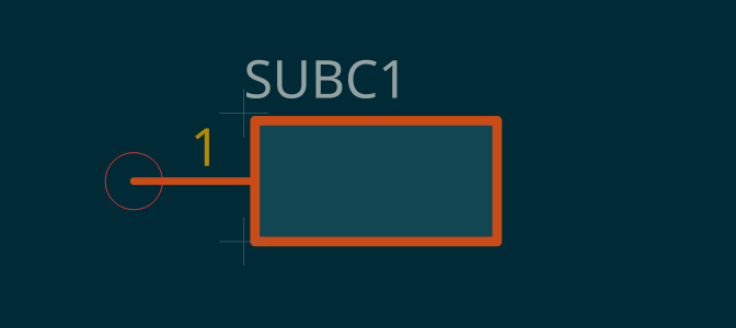 |
1 port. |
| Subcircuit 2 ports |
SUBC |
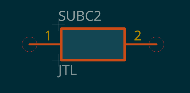 |
2 ports. |
| Subcircuit 3 ports |
SUBC |
 |
3 ports. |
| Subcircuit 4 ports |
SUBC |
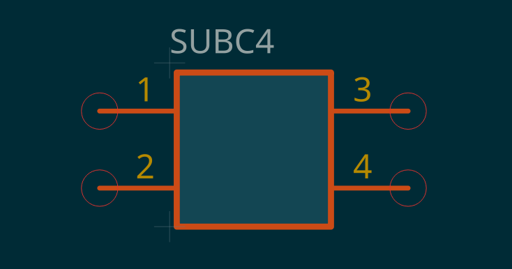 |
4 ports. |
| Subcircuit 6 ports |
SUBC |
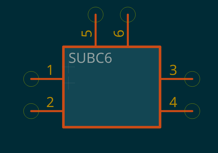 |
6 ports (all optional). |
| Subcircuit 8 ports |
SUBC |
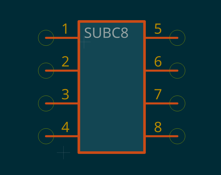 |
8 ports (all optional). |
11. Transmission lines¶
| Component Name | Prefix | Symbol | Comments |
|---|---|---|---|
| Transmission Line |
T |
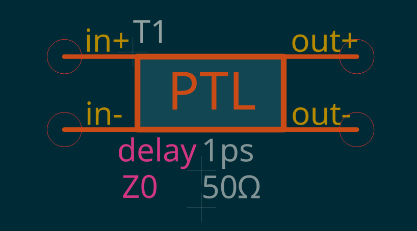 |
Ideal lossless line. Pins in+, in−, out+, out−. Attributes TD (time delay ∝ length, default 1 ps) and Z0 (characteristic impedance, Ω, default 50). JSIM form: T… N1 N2 N3 N4 LOSSLESS Z0= TD=. |