JOINUS-D User Manual – v0.1¶
JOINUS-D is FrugalEDA's main desktop application. It brings together the LibrePCB schematic editor, the JSIM and JoSIM Josephson-junction circuit simulators, and the embedded FrugalPlot viewer into a single workflow: draw a superconducting circuit in LibrePCB, convert it to a SPICE netlist, simulate it, and inspect the results — all without leaving one application. On top of that it adds the margin, yield and optimization analyses a digital design flow needs.
This manual covers the windowed application. For the command-line interface, see the separate JOINUS-D CLI reference. For the SPICE syntax JOINUS-D generates, see the Superconductor library reference guide, the JSIM manual and the JoSIM documentation. For the plot viewer embedded in JOINUS-D's own Time-domain plot tab, see the FrugalPlot manual.
This is a first version of the manual: it aims to get a new user productive, not to document every dialog and preference exhaustively. It describes JOINUS-D v3.1.
Part I — Using JOINUS-D¶
1. Introduction¶
JOINUS-D sits between two worlds that don't normally talk to each other: LibrePCB, a general-purpose schematic/PCB editor with no notion of Josephson junctions or SPICE, and JSIM/JoSIM, two text-based circuit simulators with no notion of a schematic. JOINUS-D's job is to keep a schematic and its generated netlist in sync in both directions:
- Forward conversion turns a LibrePCB schematic (drawn with the Superconductor library) into a SPICE netlist for JSIM or JoSIM.
- Back-annotation takes a netlist you've hand-edited and writes the changed values back into the LibrePCB schematic's component attributes.
- Simulation runs the netlist through JSIM or JoSIM and shows the result inline, in an embedded FrugalPlot view.
- Margin, yield and optimization analysis run the same simulation repeatedly while varying component values, to characterize how robust a design is.
JOINUS-D also manages where all of this lives on disk — two separate workspaces (one for LibrePCB projects, one for JOINUS projects) kept deliberately apart, with an explicit, tracked link between a circuit's two halves. Section 4 covers this in depth; it's worth reading even if you only use a fraction of it, since most confusing moments in JOINUS-D trace back to the handful of rules explained there.
2. Key Concepts¶
| Term | Meaning |
|---|---|
| JOINUS project | A folder under the JOINUS workspace's projects/ folder, holding one or more circuits (.cir files), a subcircuits/ folder, a technology/ folder, and a hidden .joinus file that records which circuits are paired with which LibrePCB schematics. |
| LibrePCB project (shown in the app as a schematic) | A folder under the LibrePCB workspace's projects/ folder, holding a schematic, a board, and the circuit netlist LibrePCB derives from them. |
| Circuit | One SPICE netlist (.cir), optionally paired with one LibrePCB schematic. A JOINUS project can hold several circuits. |
| Pairing | The link between a circuit's SPICE side and its LibrePCB side, recorded in the project's .joinus file. Pairing is one-to-one and workspace-global: a given LibrePCB schematic can be paired with at most one circuit, in at most one JOINUS project, at any time. |
| Subcircuit | A reusable circuit block, created with the "Convert to a Subcircuit" conversion option and stored under a project's subcircuits/ folder. Subcircuit references are resolved by internal ID, not by name, so renaming a subcircuit component doesn't break the link (see Section 11). |
| Workspace | The root folder JOINUS-D (or LibrePCB) keeps all of its own projects under. There are two — the JOINUS workspace and the LibrePCB workspace — both configurable in Preferences ▸ Workspace & conversion (Section 10.1). |
Two rules fall out of this and are enforced everywhere, automatically:
- A JOINUS project always lives inside the JOINUS workspace's own
projects/folder. You never manually place one anywhere else. - A LibrePCB project always lives inside the LibrePCB workspace's own
projects/folder. Same rule, other side.
If you point JOINUS-D at a file that lives outside the right workspace, it doesn't start treating that outside location as part of the workspace. It copies the file (or the whole project folder) in and works with that copy from then on — your original is left untouched, and a notification tells you where the copy landed. Section 4 calls this the workspace's "copy-in guard."
3. The Main Window¶
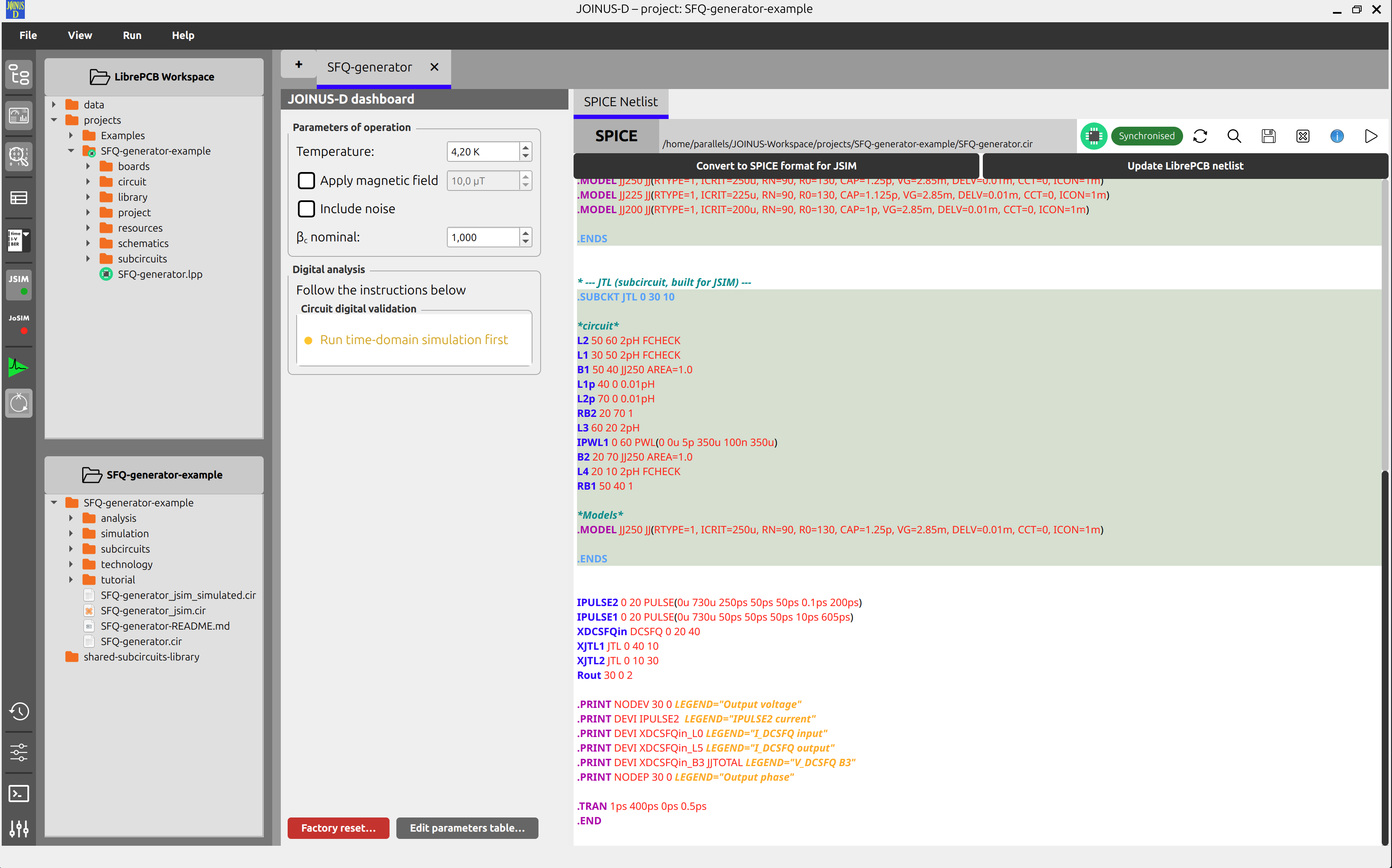 Figure: the main window with a circuit open. Numbered regions are described below.
The menu bar holds File, View, Run and Help, plus a Settings action at the bottom of the File menu (Section 8). A vertical toolbar down the left edge mirrors the View toggles and carries the simulation controls. A status bar at the bottom shows the status tip of whatever menu item is under the pointer.
3.1. Editor panes and result tabs¶
Each open circuit is its own tab. Inside a circuit's tab, JOINUS-D splits the view into a LibrePCB pane and a SPICE pane side by side, each carrying its own Convert-to-SPICE / Back-annotate control that reflects whether that side is in sync with the other.
Below the two panes, a row of result tabs holds:
- LibrePCB Netlist — a read-only view of the netlist LibrePCB itself derives from the schematic. Hidden by default (View ▸ Show LibrePCB Netlist tab).
- SPICE Netlist — the generated JSIM/JoSIM netlist text (an unsaved edit is marked with
*). - Time-domain plot — simulation output, rendered by the embedded FrugalPlot view (see Section 6).
- Margins / Optimized margins — results from the analyses in Section 7.
- Digital reference — added on demand for circuits that have one.
3.2. Side panels¶
A vertical toolbar (and matching View menu items) toggles:
- Workspace overviews panel — file trees for the current LibrePCB and JOINUS projects.
- Dashboard panel — console/log output, the simulation-type selector, and the margin / yield / optimization and digital-reference controls.
- Circuit parameters table — a table view of the circuit's component values; shares its column with the dashboard, so turning one on turns the other off.
- Digital analysis — a section inside the dashboard, toggled independently (turning it on also reveals the dashboard if the parameters table was showing).
- Conversion parameters panel — see Section 9.
- History panel — the conversion / back-annotation history of the current circuit.
The View menu also carries Show LibrePCB Netlist tab, described above.
4. Files & Projects¶
This section explains how JOINUS-D organizes your work on disk, what pairing means in practice, and how to create, open, duplicate, rename, delete, close and save projects and circuits.
4.1. The idea in one paragraph¶
A JOINUS project groups the netlists of one or several circuits, their shared subcircuits, and everything simulation derives from them. A LibrePCB project holds a circuit's schematic and the netlist LibrePCB derives from it. The two are deliberately kept as separate projects, in two separate workspaces — but JOINUS-D links a given circuit's SPICE side to its LibrePCB side through pairing, and keeps the two synchronized. A single JOINUS project can contain several circuits, each paired with its own LibrePCB schematic; a given LibrePCB schematic, however, can only ever be paired with one circuit at a time, in one JOINUS project — see Section 4.5 for what that means when you want to reuse a schematic elsewhere.
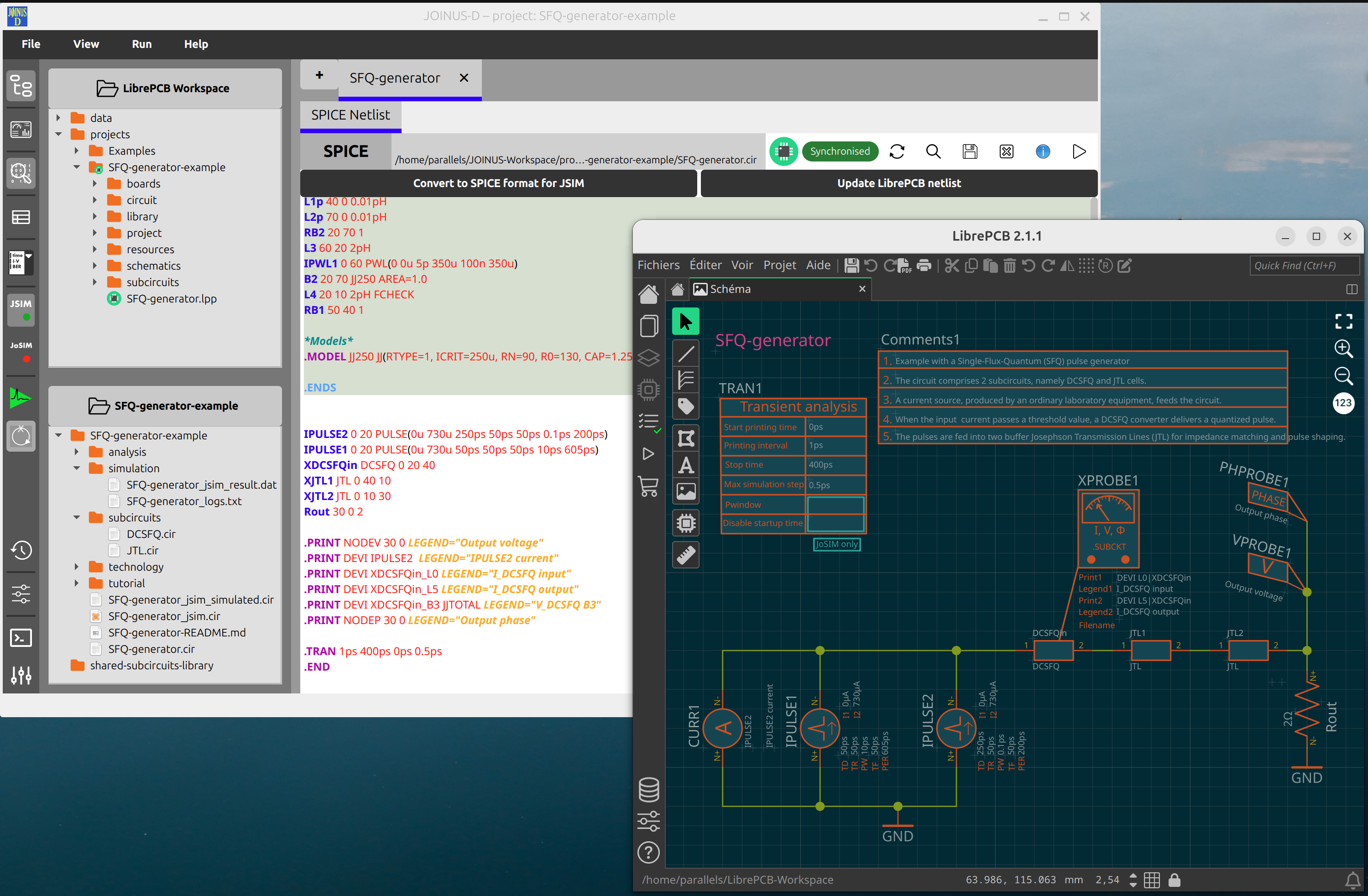 Figure: a JOINUS project and a LibrePCB project always stay inside their own workspace. Pairing is only a link — recorded in a hidden
 .joinus file — never a copy or a move.
4.2. The Welcome screen¶
The Welcome screen is what you see whenever no circuit editor is on screen — either because no project is open yet, or because the current project has no circuit tabs open.
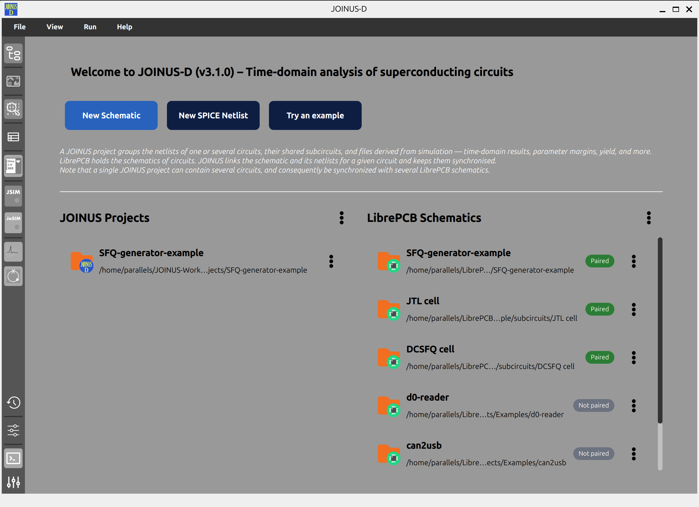 Figure: the Welcome screen with no project open. Three actions: New Schematic, New SPICE Netlist, Try an example.
With no project open, three actions are offered: New Schematic (Ctrl+Shift+N), New SPICE Netlist (Ctrl+Alt+N), and Try an example.
Once a project is open, New Schematic and New SPICE Netlist reappear, alongside Close current project.
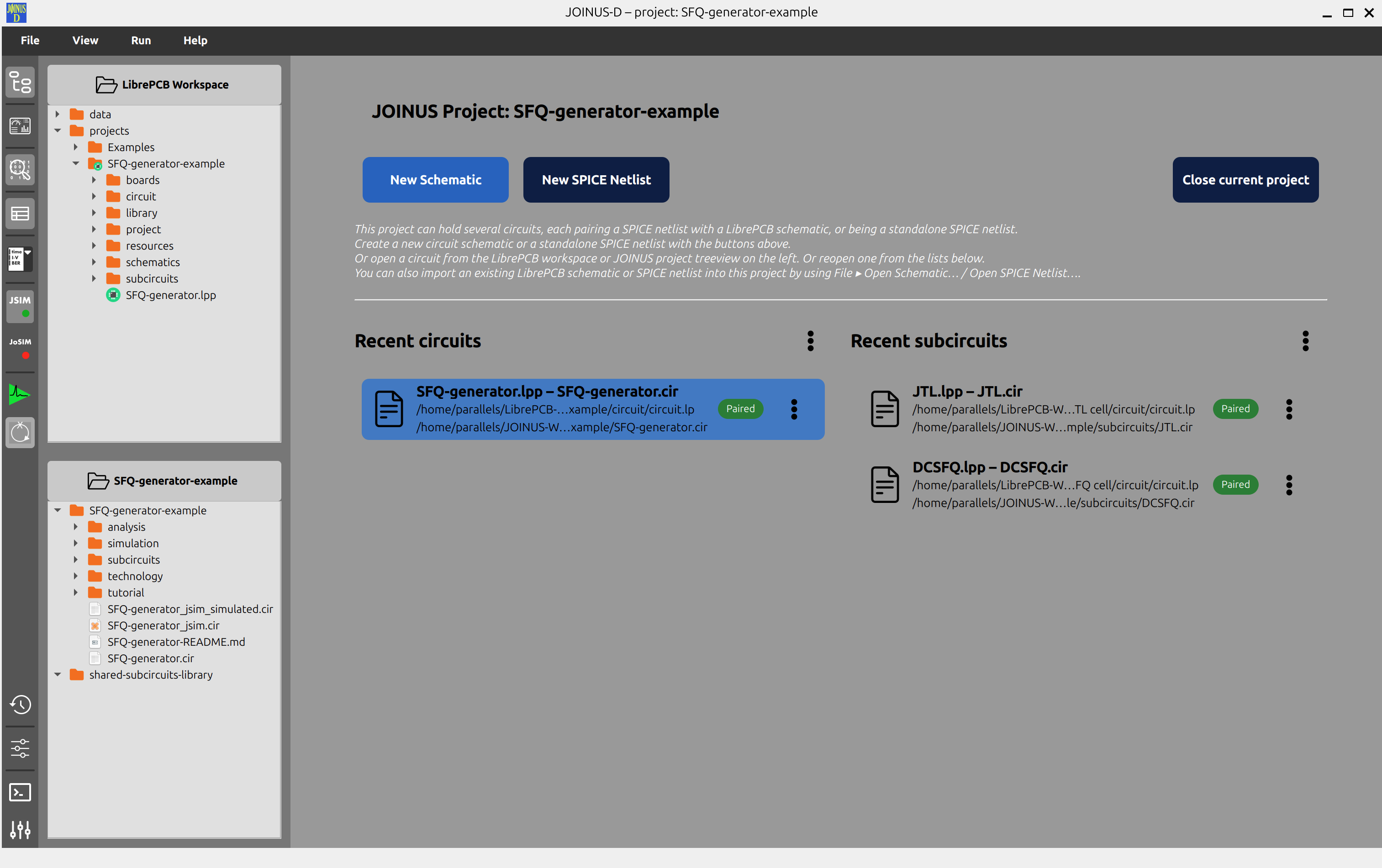 Figure: the same screen once a project is open but has no circuits yet — the same two "New…" actions now act on the current project, alongside Close current project.
The same actions are on the File menu, with the keyboard shortcuts listed in Section 8.1 — worth learning once you know your way around.
4.3. Creating a project¶
File ▸ New JOINUS Project… (Ctrl+N) asks for a name and creates the project folder directly under the JOINUS workspace's projects/ folder, along with its subcircuits/ and technology/ subfolders, and an empty .joinus pairing file. Nothing else is created until you actually add a circuit to it.
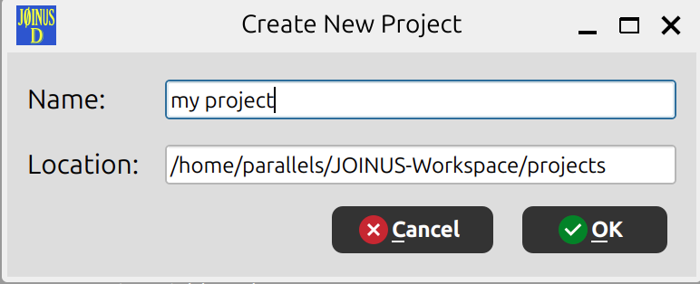
You rarely need this on its own: creating or opening a schematic or netlist when no project is open (below) offers to create a JOINUS project for you as part of that flow.
4.4. Creating or opening a schematic or netlist¶
- New Schematic… (
Ctrl+Shift+N) scaffolds a new, empty LibrePCB project and opens it in LibrePCB. - Open Schematic… (
Ctrl+Shift+O) opens a file picker for an existing LibrePCB project. If it isn't already inside the LibrePCB workspace, the whole project folder is copied in first (see Section 2) — you'll see a notification telling you where the copy landed. - New SPICE Netlist… (
Ctrl+Alt+N) creates a blank circuit tab; nothing is written to disk until you save. - Open SPICE Netlist… (
Ctrl+Alt+O) opens a file picker for an existing.cirfile. If it isn't already inside the current JOINUS project, a copy is placed inside the project folder and opened from there.
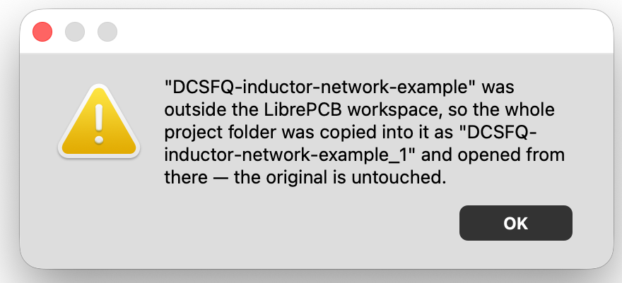
Figure: whenever a file gets copied in like this, a notification tells you the new location — your original file is never touched or deleted.
Opening or creating a schematic always converts it to SPICE immediately — there is no "auto-convert" preference to turn this off. Whether LibrePCB's own window also launches alongside it is a preference — see Section 10.4.
4.5. Pairing¶
Pairing is the link between a circuit's SPICE side and its LibrePCB side. You rarely manage it directly — it's established automatically the first time a circuit's two sides come together, and from then on JOINUS-D keeps opening both sides together, keeps the link intact through renames, and enforces that it stays one-to-one.
What happens when you open a LibrePCB schematic depends on whether it's already paired:
- Not paired with anything yet — you're asked to choose: Create New JOINUS Project, or Add to Existing JOINUS Project.
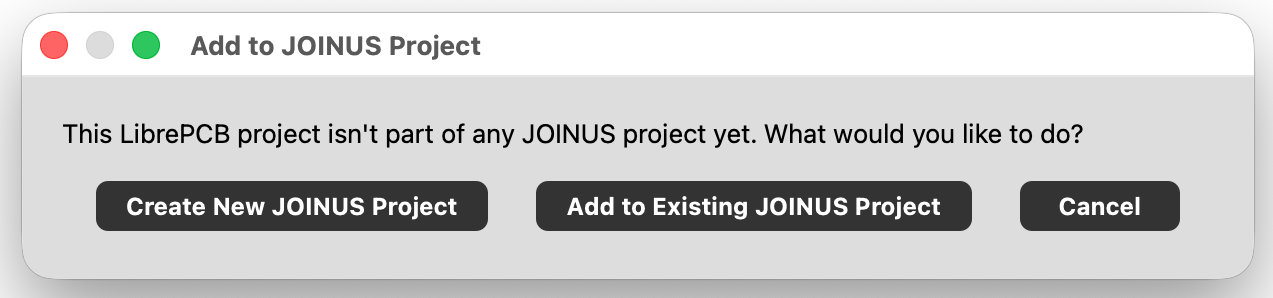
Picking "Add to Existing" shows a picker of your current JOINUS projects:
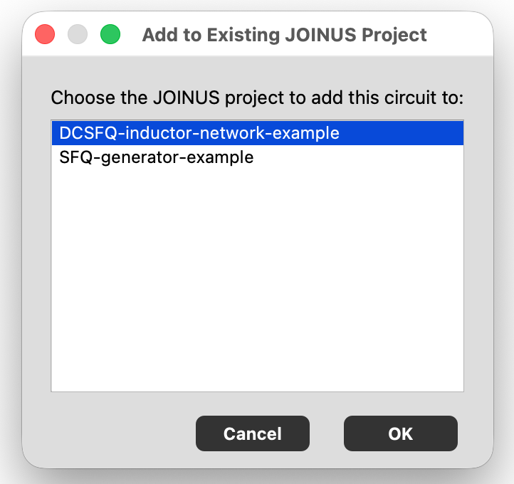
- Already paired with a JOINUS project — opening it takes you straight to the paired circuit. No question asked — this is the common case of simply reopening something you've already set up.
Because pairing is enforced one-to-one across the whole workspace, a schematic that's already paired can't be paired again elsewhere. To reuse a schematic in a second design — a shared building block, a standard cell — duplicate it first: from the LibrePCB Schematics list's ⋮ menu, Duplicate into another JOINUS project… makes an independent copy with its own identity, and offers that copy for pairing.
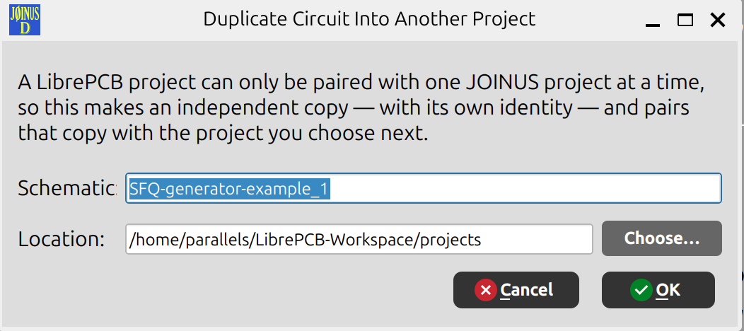
Open SPICE Netlist… follows the identical logic for a bare .cir file that isn't already inside a tracked JOINUS project: if it's already sitting inside one of your project folders, it opens there directly; otherwise you get the same Create New / Add to Existing choice.
Both the Recent circuits and LibrePCB Schematics lists on the Welcome screen show a Paired / Not paired badge on every row, with a tooltip on hover naming exactly what it's paired with.
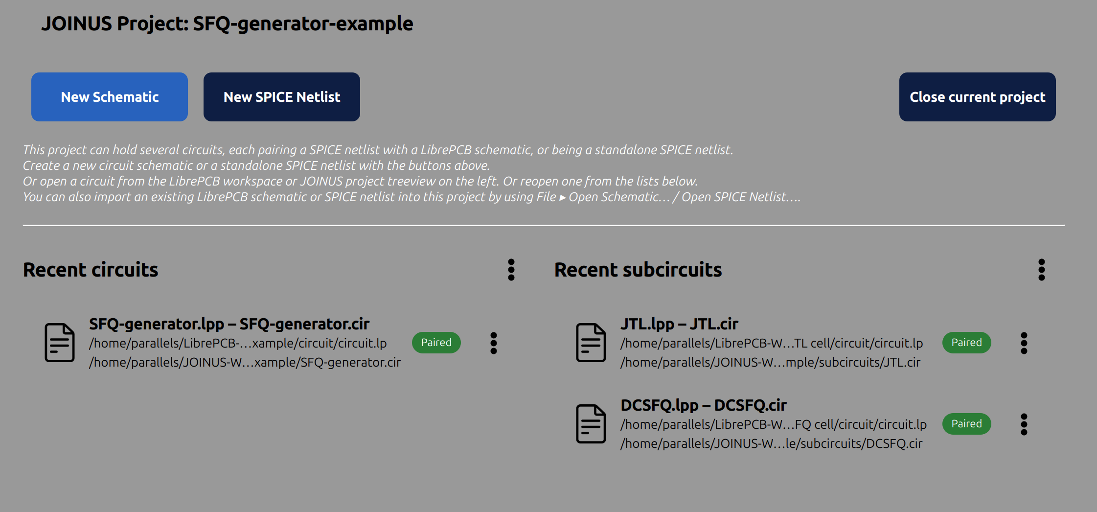
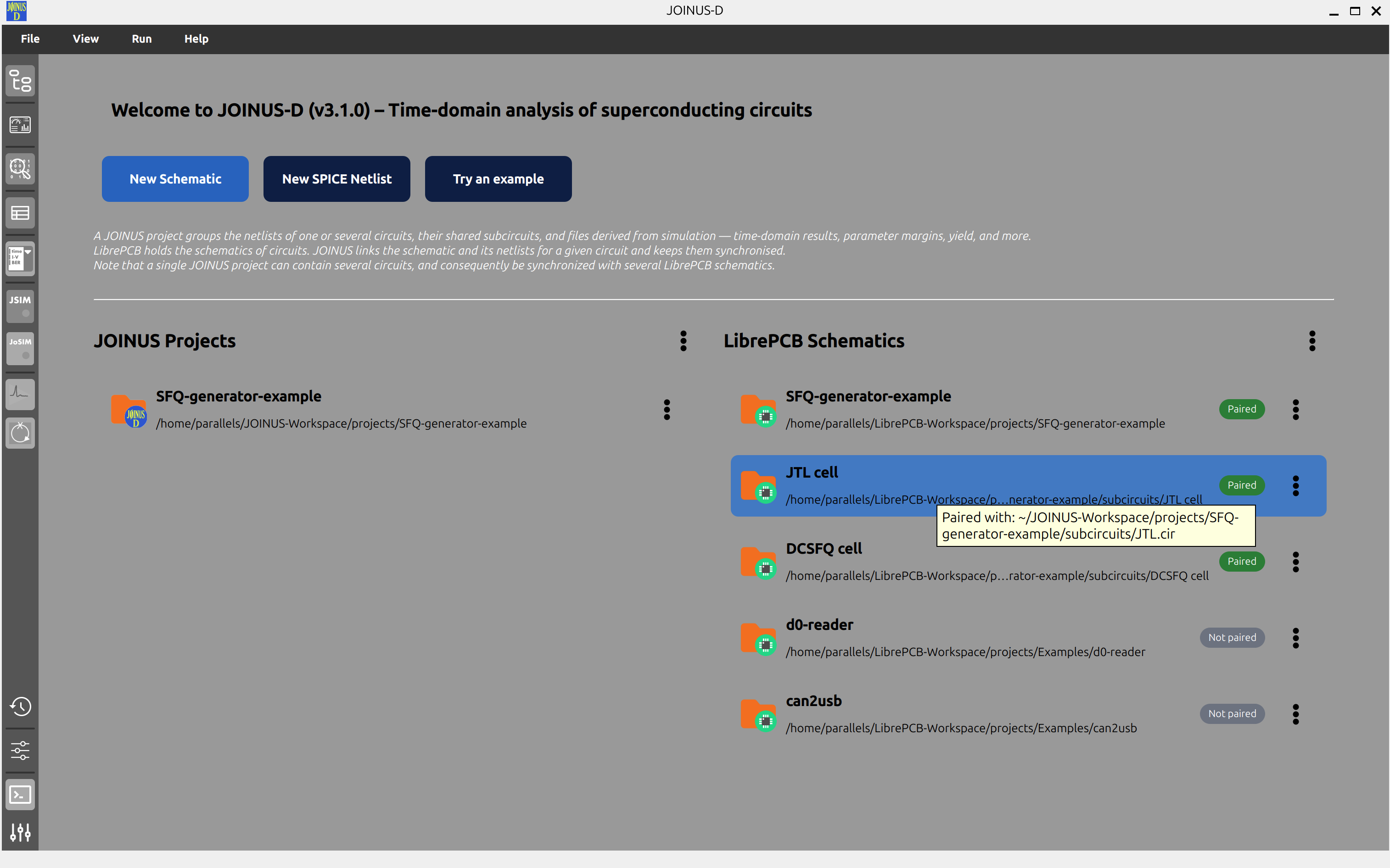
Note: you may occasionally still see a "this schematic is paired with more than one project — pick one" prompt. That's a legacy fallback for data created before one-to-one pairing was enforced (or edited by hand); it is not a normal way to create a new multi-pairing, since new pairing attempts are refused once a schematic already has an owner.
4.6. Opening things¶
File ▸ Open JOINUS Project… (Ctrl+O) opens a folder picker rooted at the JOINUS workspace. If the project has more than one circuit, you're asked which ones to open, with Select All / Select None shortcuts for large projects:
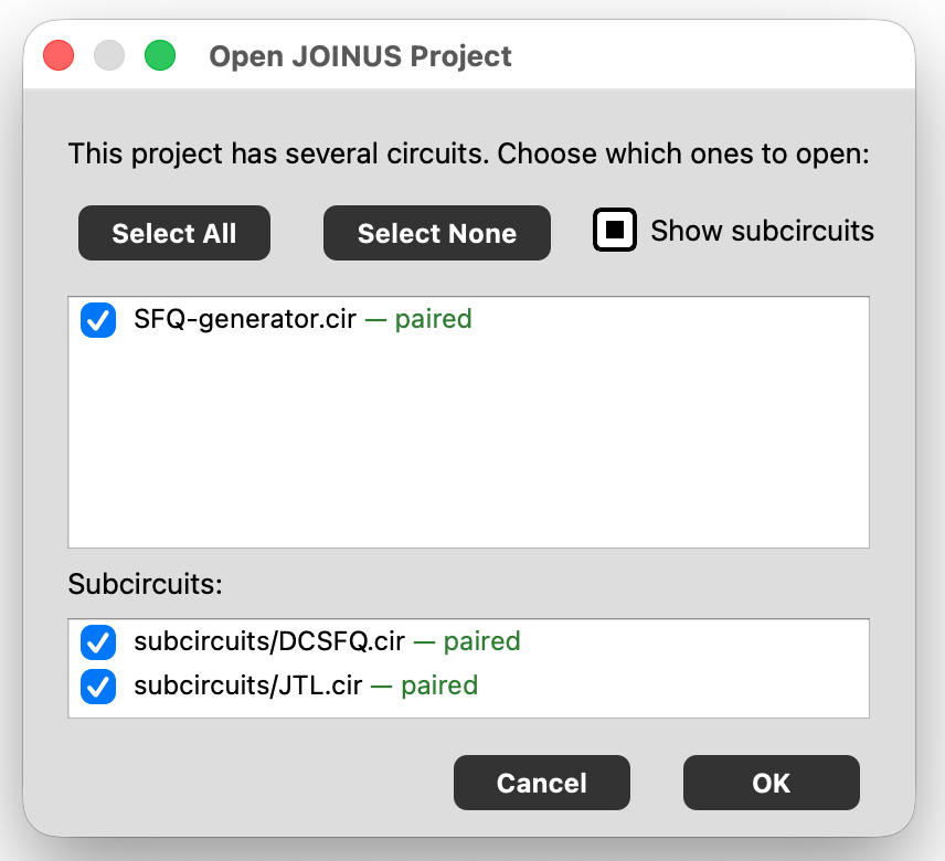
A project with a single circuit skips this picker and opens it directly.
Clicking a row in Recent circuits reopens that exact circuit in the current project. Clicking a row in JOINUS Projects or LibrePCB Schematics (shown before any project is open) opens that project or schematic.
4.7. Trying an example¶
Try an example copies one of the bundled, read-only example projects into your workspace as an ordinary, fully editable project — the original example is never modified, so you can always go back and copy it again with a fresh start. The same action is also on the Help menu.
4.8. Duplicating¶
Every JOINUS project, and every individual circuit file, can be duplicated from its ⋮ menu.
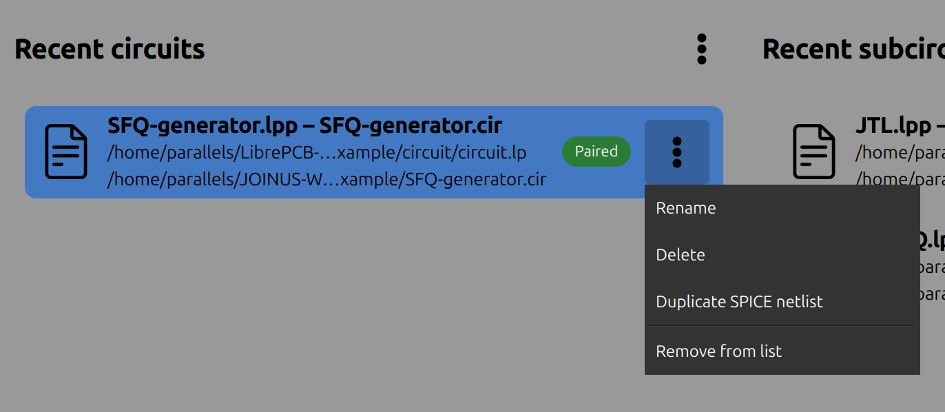
Duplicating a JOINUS project duplicates its SPICE side and an independent copy of every LibrePCB schematic it's paired with — the duplicate gets its own, separate LibrePCB project folders and its own pairing, not a shared reference to the originals. Editing the schematic in the duplicated project never affects the original, and vice versa.
Duplicating a single circuit file just copies that one .cir file under a collision-free name in the same folder; it has no LibrePCB side to duplicate along with it.
4.9. Renaming¶
Renaming a JOINUS project folder, a LibrePCB project folder, or an individual circuit file is always safe: JOINUS-D automatically updates every affected pairing behind the scenes, so nothing gets silently unpaired by a rename. Renaming a LibrePCB project folder also keeps its internal project file and its display name (the one LibrePCB itself shows) in sync with the new folder name.
4.10. Deleting¶
Deleting a JOINUS project (via its ⋮ menu) asks for confirmation first, since it's not recoverable — the whole folder, and every circuit inside it, is removed immediately. Its paired LibrePCB schematic, if any, is not deleted — deleting one side can never be assumed safe for the other. If you also want the LibrePCB schematic gone, delete it separately from the LibrePCB Schematics list.
Remove from list / Clear list, on the Recent circuits or Recent subcircuits columns, is not deletion — it only hides entries from that view. The underlying files and their pairing are left completely untouched, and opening a hidden circuit again automatically un-hides it.
4.11. Closing¶
Close current project / File ▸ Close JOINUS Project (Ctrl+F4) checks every circuit tab for unsaved changes first; if there are any, you're offered Save, Discard, or Cancel before the project actually closes.
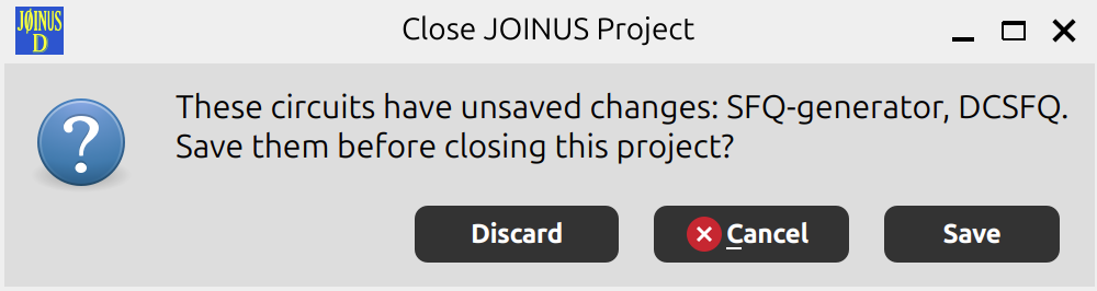
Close Circuit closes just the current tab, with the same guard. Closing a circuit never touches its pairing — closing and reopening a circuit always finds its LibrePCB side again.
4.12. Saving¶
Save Circuit (Ctrl+S) writes both sides of the current circuit (whichever have unsaved changes). Save JOINUS Project saves every circuit in the project.
Save Circuit As… does not relocate the current circuit — it forks a new, independent copy under a name you choose. You are asked only for one new name; there is no folder picker. From that name, a new SPICE netlist is written into the current JOINUS project and — if there's a real LibrePCB schematic behind it — a new LibrePCB project is created under the same name in the LibrePCB workspace, with a fresh identity of its own. The original stays exactly where it was, still registered in the project, and the editor tab switches to the new fork. (A circuit that has never been saved before saves in place, since there's nothing yet to fork from.)
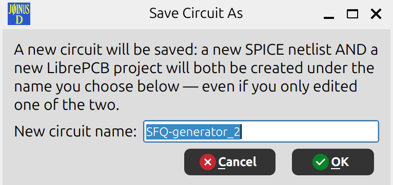
Because both halves are placed automatically — the SPICE side inside the current JOINUS project, the LibrePCB side inside the LibrePCB workspace's projects/ folder (Section 2) — you can't save the fork somewhere the app couldn't track. If a computed destination would somehow fall outside its workspace, the save is refused with an Invalid Location message.
4.13. Quick reference¶
| I want to… | Where to find it |
|---|---|
| Start a brand-new, empty schematic | New Schematic… (Ctrl+Shift+N) |
| Start a brand-new, empty netlist | New SPICE Netlist… (Ctrl+Alt+N) |
| Open an existing LibrePCB schematic | Open Schematic… (Ctrl+Shift+O) |
| Open an existing SPICE netlist | Open SPICE Netlist… (Ctrl+Alt+O) |
| Create an empty JOINUS project directly | File ▸ New JOINUS Project… (Ctrl+N) |
| Reuse a schematic in a second JOINUS project | LibrePCB Schematics list ▸ ⋮ ▸ Duplicate into another JOINUS project… |
| Open a project with several circuits | File ▸ Open JOINUS Project… (Ctrl+O), then pick circuits |
| Reopen a specific circuit | Click it under Recent circuits |
| Copy a project (SPICE + LibrePCB sides, independently) | Project's ⋮ menu ▸ Duplicate |
| Rename anything | ⋮ menu ▸ Rename — pairing is preserved automatically |
| Delete a project | Project's ⋮ menu ▸ Delete (asks to confirm; LibrePCB side untouched) |
| Hide a circuit from Recent circuits without deleting it | Row's ⋮ menu ▸ Remove from list |
| Save a circuit as an independent copy | Save Circuit As… |
| Fix projects copied outside JOINUS-D that share an identity | File ▸ Check Workspace Duplicate Identities… |
4.14. Frequently asked questions¶
Why was my file copied instead of opened in place? Because it wasn't already inside the right workspace. JOINUS-D never tracks a file from an arbitrary location on disk — it copies it into the workspace first, so the Welcome screen's lists, pairing, and every other feature that assumes "this project lives under the workspace" keep working correctly. Your original file is left exactly where it was.
Why did opening a schematic not ask me anything? Because it was already paired with a JOINUS project — JOINUS-D took you straight there. See Section 4.5 for the full decision flow.
I deleted a JOINUS project — where did its LibrePCB schematic go? Nowhere — it's untouched. Delete it separately from the LibrePCB Schematics list if you no longer need it.
Can I reuse the same schematic in two different JOINUS projects? Not directly — pairing is strictly one-to-one, enforced across your whole workspace, not just within a project. To reuse a schematic elsewhere, duplicate it first (Duplicate into another JOINUS project…); the duplicate gets its own identity and can be paired independently. See Section 4.5.
5. Converting a Schematic¶
5.1. Forward conversion — LibrePCB to SPICE¶
Conversion runs automatically whenever a schematic is created, opened, or edited and saved — there is no separate "convert" step to remember for the common case. A manual re-convert action stays available in each pane's heading for re-syncing after external changes. How the netlist is shaped is controlled by the conversion parameters panel.
5.2. Back-annotation — SPICE to LibrePCB¶
Editing the generated netlist by hand (adding a .PRINT line, tweaking a .MODEL parameter, …) and wanting those edits reflected back in the schematic's component attributes is back-annotation. Unlike forward conversion, it is always an explicit action — JOINUS-D never silently rewrites your schematic — offered when the SPICE side is "ahead" of the LibrePCB side. It's also available headlessly from the command line (-i circuit.cir -o schematic.lp, see Section 12).
6. Running a Simulation¶
Run ▸ Simulate (F10) runs the current circuit's netlist through the active simulator. A toggle on the left toolbar switches which simulator is active — JSIM or JoSIM — without needing to reconvert first; the default simulator and JoSIM's output file extension are set in Preferences ▸ Workspace & conversion.
Results appear directly in the Time-domain plot tab, rendered by an embedded FrugalPlot view — the same plotting engine and interface FrugalPlot's own manual documents, just docked inside JOINUS-D instead of running as a separate window. Console/log output from the simulation run appears in the dashboard panel (Section 3.2).
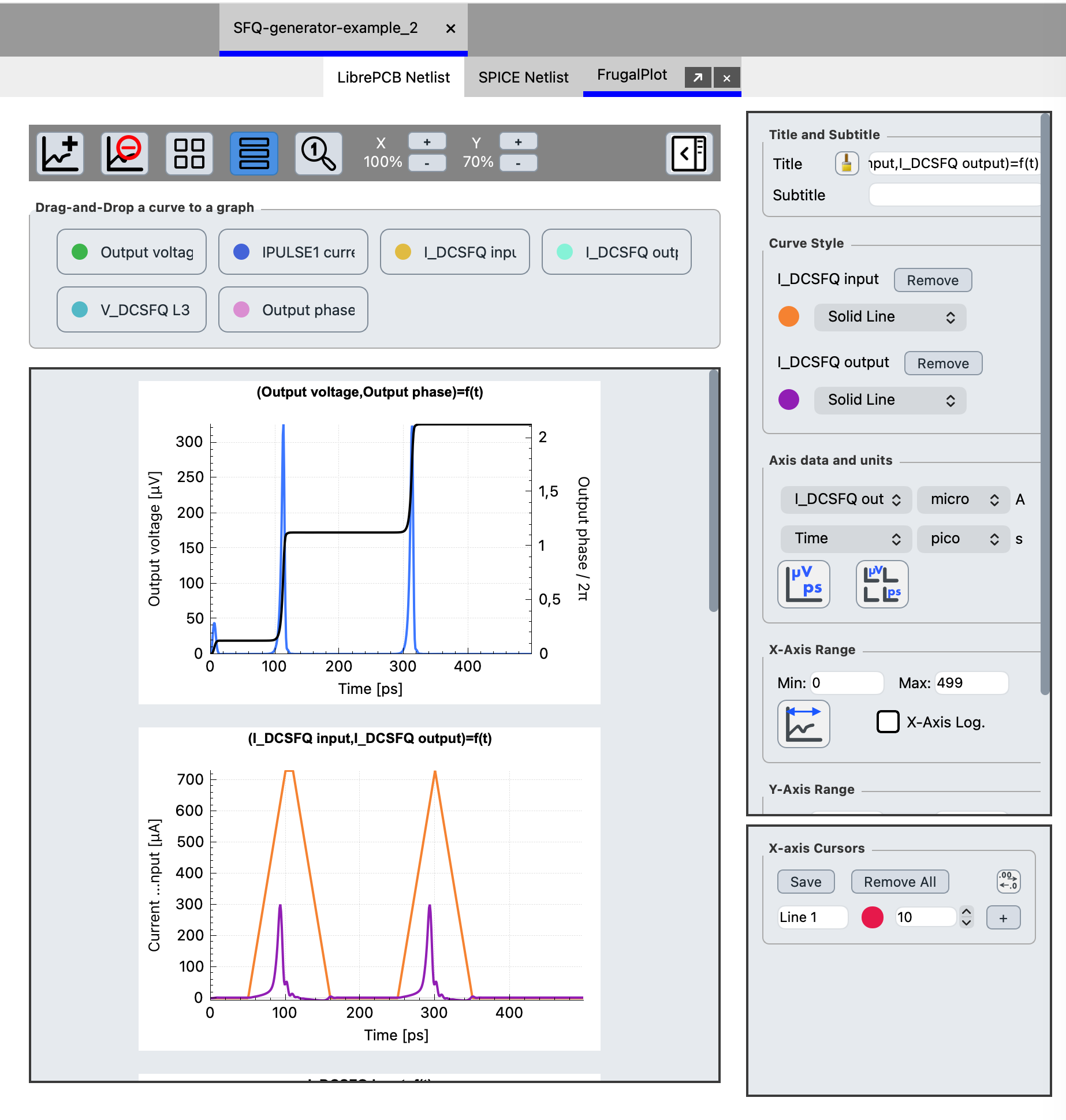 Figure: simulation results, shown inline using the same FrugalPlot interface described in its own manual.
The dashboard's simulation-type selector also lists Parametric, Temperature, BER, Frequency and I-V sweeps. In v3.1 only Time domain is wired to the plot view; the others are placeholders for a later release.
7. Margins, Yield and Optimization¶
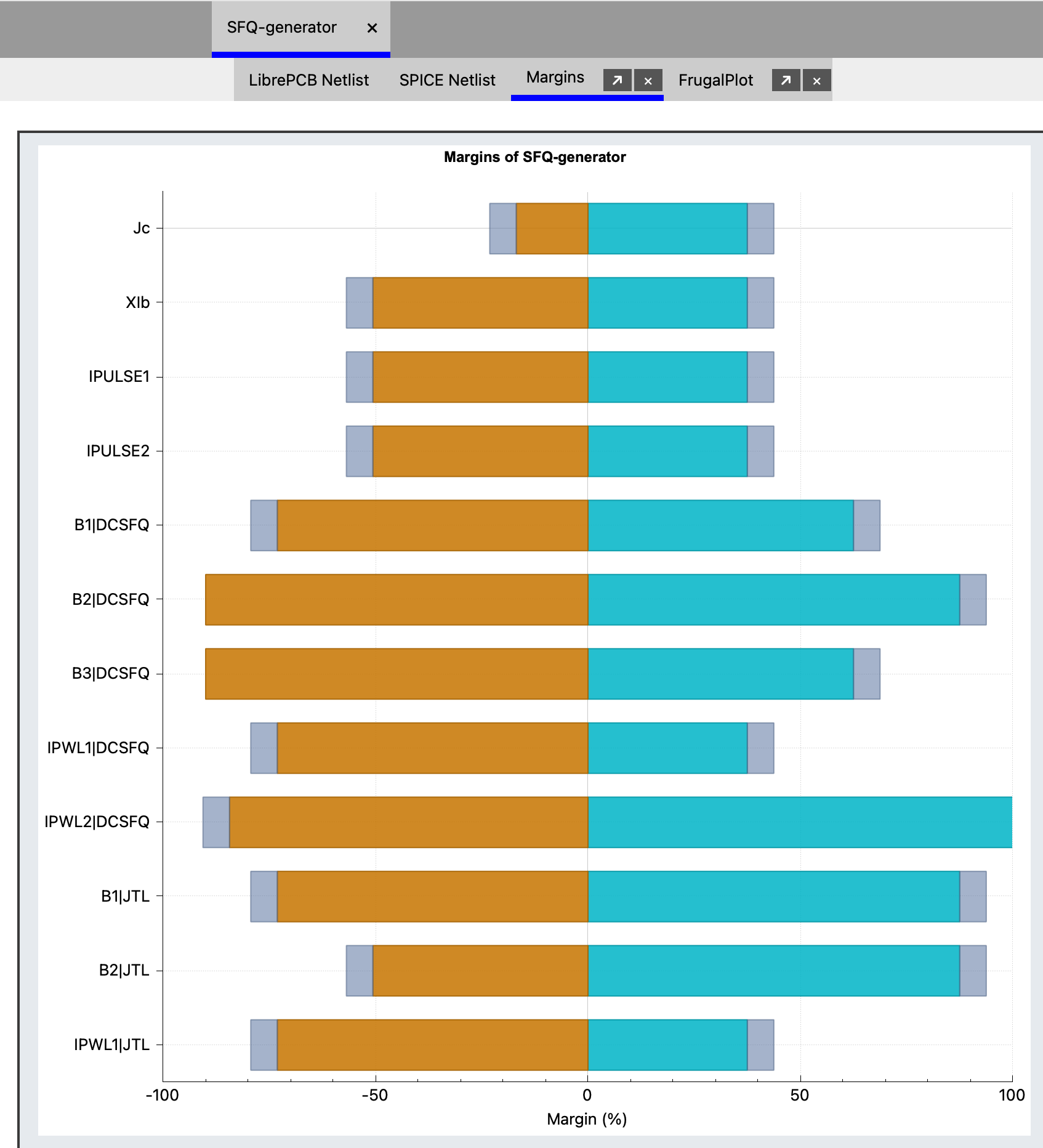
Beyond a single simulation run, JOINUS-D can repeatedly re-simulate a circuit while varying component values, to characterize how robust a design is to fabrication spread. The controls are in the dashboard panel (Section 3.2); results open in their own result tabs:
- Margins — sweeps individual parameters to find the range over which the circuit still works correctly, shown in the Margins tab.
- Optimized margins — searches for parameter adjustments that widen those margins, shown in the Optimized margins tab.
- Yield — estimates the fraction of fabricated circuits that would work, given the parameter spread.
All three use the sigma and default values set under Preferences ▸ Other parameters (Section 10.3) unless overridden per run. A circuit's expected logic can be checked against a Digital reference file loaded from the same panel.
Part II — Reference¶
8. Menus¶
The menu bar holds File, View, Run and Help.
8.1. File menu¶
| Item | Shortcut | Action |
|---|---|---|
| New JOINUS Project… | Ctrl+N |
Create an empty project under the JOINUS workspace. |
| Open JOINUS Project… | Ctrl+O |
Open an existing project; if it holds several circuits you choose which to open. |
| Save JOINUS Project | Save every circuit in the project. | |
| Close JOINUS Project | Ctrl+F4 |
Close the project and return to the Welcome screen. |
| New Schematic… | Ctrl+Shift+N |
New circuit + its LibrePCB schematic, opened in LibrePCB. |
| Open Schematic… | Ctrl+Shift+O |
Open a LibrePCB project as a circuit; one outside the LibrePCB workspace is copied in first. |
| Check Workspace Duplicate Identities… | Scan the LibrePCB workspace for project folders copied outside JOINUS-D that share an identity, and give each its own so all can be paired. | |
| New SPICE Netlist… | Ctrl+Alt+N |
New blank SPICE-netlist circuit, no schematic. |
| Open SPICE Netlist… | Ctrl+Alt+O |
Open a .cir file as a circuit; a file outside the project is copied in first. |
| Save Circuit | Ctrl+S |
Save this circuit's netlist and, if present, its schematic. |
| Save Circuit As… | Fork an independent copy of the circuit — SPICE side plus its LibrePCB project — under a new name (Section 4.12). | |
| Close Circuit | Close the current circuit tab. | |
| Last / Previous / Next netlist | Ctrl+↓ / Ctrl+← / Ctrl+→ (⌘ on macOS) |
Step through the circuit's conversion history. |
| Settings | F8 |
Open the Preferences dialog (Section 10). |
8.2. View menu¶
Toggles, each mirrored by a button on the left toolbar:
- Show workspace overviews panel
- Show dashboard panel
- Show digital analysis (a section inside the dashboard)
- Show circuit parameters table (shares the dashboard's column)
- Show history panel
- Show conversion parameters panel
- Show LibrePCB Netlist tab
See Section 3.2.
8.3. Run menu¶
Simulate (F10) — run the active simulator on the current netlist (Section 6). The active simulator is switched from the left toolbar; its default is in Preferences.
8.4. Help menu¶
JOINUS-D Documentation and LibrePCB Documentation (open the online docs in your browser), Try an example (same as the Welcome-screen action, Section 4.7), About JOINUS-D, and About Qt.
9. Conversion Parameters Panel¶
View ▸ Show conversion parameters panel controls how a schematic is turned into a netlist. The options apply to the next conversion.
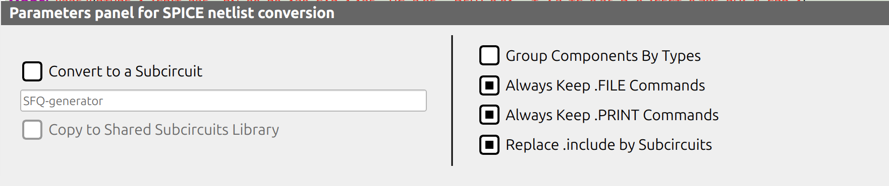 Figure: the conversion parameters panel, docked next to the workspace.
| Section | Option | Effect |
|---|---|---|
| Subcircuit | Convert to a Subcircuit (+ name field) | Convert this circuit as a .SUBCKT block — see Section 11. |
| Copy to Shared Subcircuits Library | Also save the subcircuit to the shared library for reuse across projects. | |
| Output | Group Components By Types | Order the generated netlist by component type rather than schematic order. |
| Always Keep .FILE Commands | Preserve .FILE output redirections across reconversion even if nothing currently requires them. |
|
| Always Keep .PRINT Commands | Same for .PRINT lines. |
|
| Replace .include by Subcircuits | Inline referenced subcircuits directly into the netlist instead of .include-ing them, producing one self-contained file (same as the CLI's -e/--expand, Section 12). JoSIM-only; JSIM output is always fully expanded regardless. |
10. Preferences¶
Settings (F8) opens the Preferences dialog, split into four tabs.
10.1. Workspace & conversion¶
![Preferences — Workspace & conversion tab]](../../content/joinus/preferences_workspace_tab.png)
- JOINUS workspace — its name and location; rename in place, or Move / Archive / Duplicate the whole workspace.
- LibrePCB workspace — its location.
- Include a header comment in the generated netlist + Header pattern — a comment block prepended to converted netlists (placeholders: conversion time, project name, simulator).
- Default supply voltage (VCC) — LibrePCB's generic VCC power symbol can be used directly as a DC supply. On conversion, a component placed with the value VCC becomes a DC voltage source to ground at this value, written in the form JSIM or JoSIM expects. The default is 2.5 mV — a typical superconducting-electronics supply — not the 3.3 V or 5 V of semiconductor logic.
- Simulators — Default simulator (JSIM / JoSIM), JoSIM output file extension (DAT / CSV; JSIM always writes DAT), and the JSIM executable and JoSIM executable paths used by Run ▸ Simulate and the CLI.
10.2. Physical parameters¶
![Preferences — Physical parameters tab]](../../content/joinus/preferences_physical_tab.png)
Superconductor material selection, the material constants (reset automatically whenever you change the selected material), and operating conditions such as temperature (independent of the material choice). This is JOINUS-D's technology/materials surface — there is no separate standalone dialog for it.
10.3. Other parameters¶
![Preferences — Other parameters tab]](../../content/joinus/preferences_other_tab.png)
- Electrical parameter defaults.
- Josephson-junction model defaults — used when a junction has no
.MODELassigned in the schematic (see the Superconductor library reference). - Analysis defaults — the local / global sigma values, the σmax and sigma-step count for yield, and the bisection-iteration cap, all used by margin, yield and optimization runs.
10.4. Miscellaneous¶
![Preferences — Miscellaneous tab]](../../content/joinus/preferences_misc_tab.png)
- Analysis results extension (
.txt/.dat). - Console font size — point size of the dashboard console text.
- Launch LibrePCB after importing a circuit — whether LibrePCB's own window opens alongside a schematic. There is no "auto-convert" toggle to pair with it; conversion always runs (see Section 4.4).
- Show LibrePCB Netlist tab — same toggle as the View menu item.
- Default transient analysis (.TRAN) — the Tstart / print-step / Tstop / simulation-step values injected (with a
#WARNING!) when a converted schematic contains no Transient Analysis component. See the Superconductor library reference §2.6.
11. Subcircuits¶
A subcircuit is a reusable circuit block, created by enabling Convert to a Subcircuit in the conversion parameters panel and giving it a name. The result is written under the project's subcircuits/ folder and, optionally, copied into the shared subcircuits library for reuse across projects.
Subcircuits you've used recently appear in their own Recent subcircuits column on the Welcome screen, alongside Recent circuits — with the same Paired / Not paired badge conventions and Remove from list behavior described in Section 4.
A component referencing a subcircuit is bound to it by internal ID, not by name — renaming a subcircuit later doesn't break components that already reference it.
12. Command-Line Interface¶
JOINUS-D can also run headlessly from the command line for scripting and batch conversions — full reference in the JOINUS-D CLI manual. In short:
The CLI only converts — it has no equivalent of Run ▸ Simulate or the Time-domain plot tab, and no -r/-p flags. Running a simulation and viewing results requires the windowed application.
13. Getting Help¶
The Help menu (Section 8.4) links the online JOINUS-D and LibrePCB documentation, offers Try an example, and shows About dialogs for JOINUS-D and Qt.
14. Known Limitations (v3.1)¶
- The dashboard's simulation-type selector lists Parametric, Temperature, BER, Frequency and I-V alongside Time domain, but only Time domain is currently wired to the plot view.
- InductEx integration is not yet available — the per-project
inductex/folder isn't created, and there's no InductEx panel yet. - The command-line interface has no simulate or plot equivalent (Section 12) — those require the windowed application.
- This manual describes each Preferences tab's purpose rather than every individual field.
- The dashboard's analysis workflow — filling in the circuit parameters table, building a digital reference (the pass/fail criterion that margin and optimization analyses check against), and running the margin, yield and optimization analyses — is only outlined here; a step-by-step walkthrough is planned for a later revision.