Reference guide – v0.2 – 10.11.2025
Superconductor Library
The Superconductor library is dedicated to the LibrePCB schematic editor. It provides devices, models and control commands needed to simulate digital and quantum electronics circuits with either JoSIM or JSIM simulators.
Category Mapping
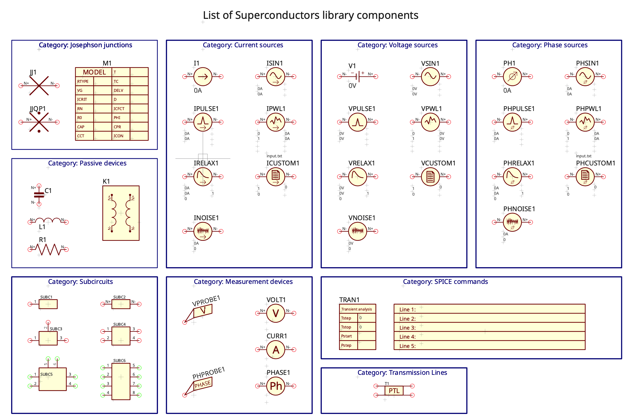
An overview of the different library components is shown below.
Components overview
| Category | Components |
|---|---|
| Josephson Junctions | Josephson Junction, Josephson Junction With Quasiparticles, Model |
| Measurement Devices | Ammeter, Voltmeter, Voltage Probe, Phasemeter, Phase Probe |
| Passive devices | Capacitor, Resistor, Inductor, Mutual Inductance |
| Signal Sources | - |
| ├─ Current Sources | Current DC, Current AC, Current Pulse, Current Relaxation, Current Noise, Current Custom Waveform, Current PWL |
| ├─ Phase Sources | Phase DC, Phase Noise, Phase Relaxation, Phase AC, Phase Pulse, Phase PWL, Phase Custom Waveform |
| └─ Voltage Sources | Voltage DC, Voltage Custom Waveform, Voltage AC, Voltage Pulse, Voltage PWL, Voltage Noise, Voltage Relaxation |
| SPICE Commands | Transient Analysis, Model, Text |
| Subcircuits | Subcircuit 1 port, Subcircuit 2 ports, Subcircuit 3 ports, Subcircuit 4 ports, Subcircuit 6 ports, Subcircuit 8 ports |
| Transmission Lines | Transmission Line |
Symbols overview
The corresponding symbols of the components are shown below.
Signal Sources
The library includes current, voltage and phase sources. Each is available in seven predefined subtypes, distinguished by their underlying waveforms and associated mathematical equations. Predefined subtypes:
- DC : constant signal
- Alternative (AC): sinusoidal signal
- Piece-Wise Linear (PWL): signal composed of linear parts
- Pulse : train of pulses (JSIM and JoSIM simulators) or unique pulse (JoSIM only)
- Noise : white noise signal
- Exponential: signal exponentially reaching a final amplitude from an initial amplitude with \(\tau\)1 time constant then relaxing back to initial amplitude with \(\tau\)2 time constant
- Custom Waveform: defined in a specific file
Each element has a set of attributes that correspond directly to the parameters used in its defining equation.
Josephson Junctions
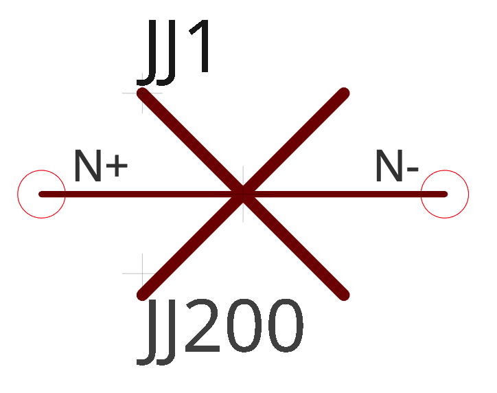
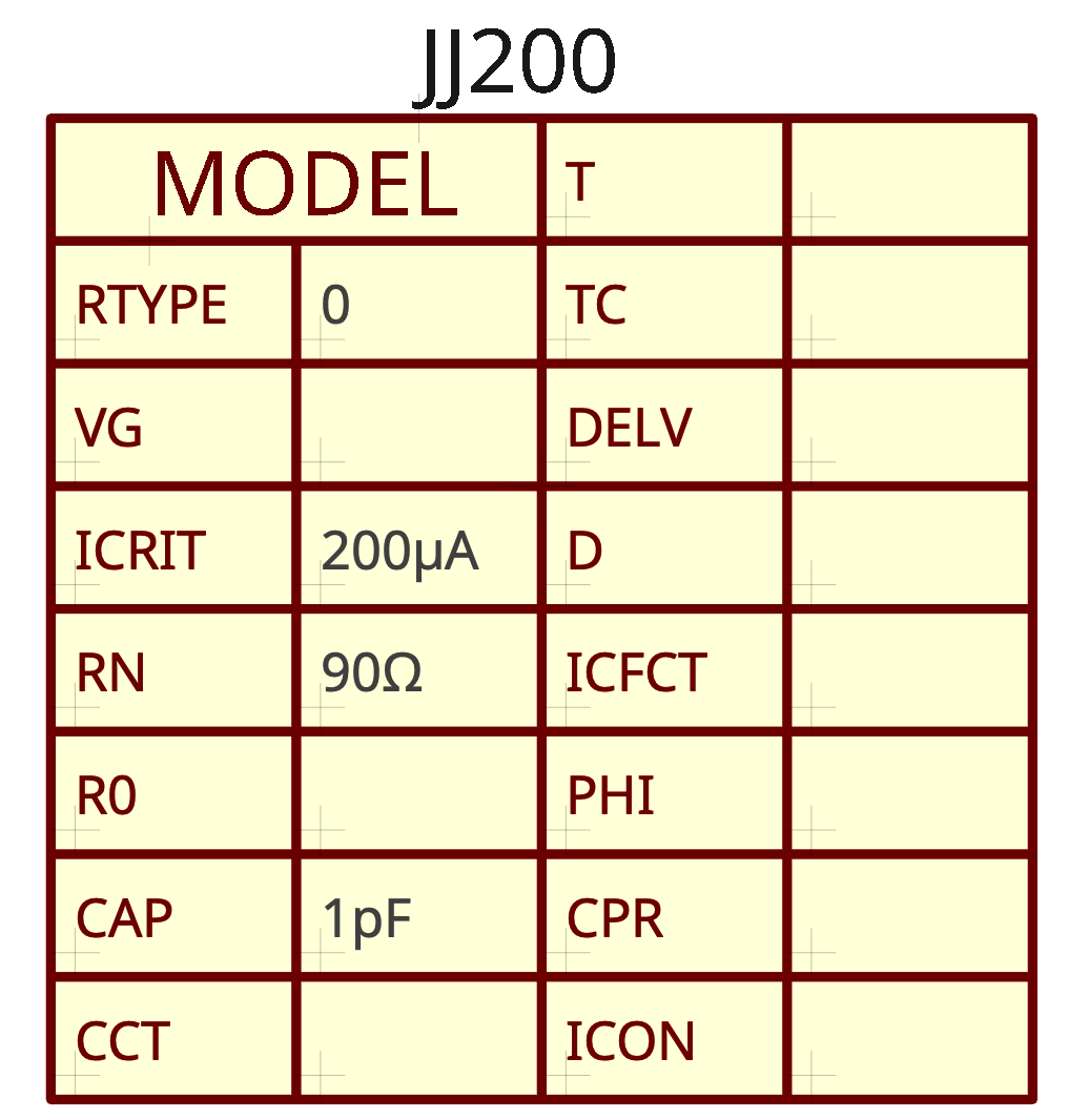
Josephson Junctions can be used only with a connected "Model" element. The model contains all possible parameters that are used by JSIM/JoSIM simulators. To connect a model to a junction, its name must be written in the junction's attributes.
 |
 |
|---|---|
| JJ1 Josephson junction with model JJ200 | Example of JJ200 .model parameters for JJ1 Josephson junction |
Control Commands
To perform a simulation, control commands must be added to the circuit along with their corresponding parameters. These commands are available under the SPICE Commands tab of LibrePCB.
Transient analysis give parameters necessary to study a circuit's behavior over time with JSIM or JoSIM simulator.
Measurement devices
To observe the simulation results, output parameters must be explicitly defined. The following elements are responsible for producing the output corresponding to the desired type of signal.
-
Ammeter
-
Voltmeter
-
Voltage probe
-
Phasemeter
-
Phase probe
Probes give signals with respect to the ground while meters give values between node N+ and node N-.
Subcircuits
Subcircuits are reusable circuit blocks that encapsulate a portion of a schematic into a single, modular component. They allow for hierarchical design, simplify complex schematics, and promote reusability across multiple projects. The Superconductor library and L2SPICE application allow for easy design and implementation of subcircuits, which can be reused to construct more complex circuits efficiently.To use a subcircuit in your design, it must first be assigned a name and saved in its SPICE-compatible form using L2SPICE.
Parameters
The parameters of each component of the library are described in the documentation of the simulators at:
- the documentation website for JoSIM simulator
- or in the original JSIM manual for JSIM simulator. The syntax for noise elements of JSIM is available in this document.
Note
Some parameters of certain Superconductor library components are not used by simulators. They are planned for further advanced functionalities of FrugalEDA.
Signal naming convention
The voltage (VN+ – VN-) is positive by convention for all voltage sources.
The phase difference (\(\phi\)N+ – \(\phi\)N-) is positive by convention for all phase sources.
The current running from node N+ to node N- inside any current source is positive by convention.
Superconductor library components
| Component Name | Prefix | Symbol | Comments |
|---|---|---|---|
| Category: | Josephson Junctions | ||
| Josephson Junction With Quasiparticles | JJQP | 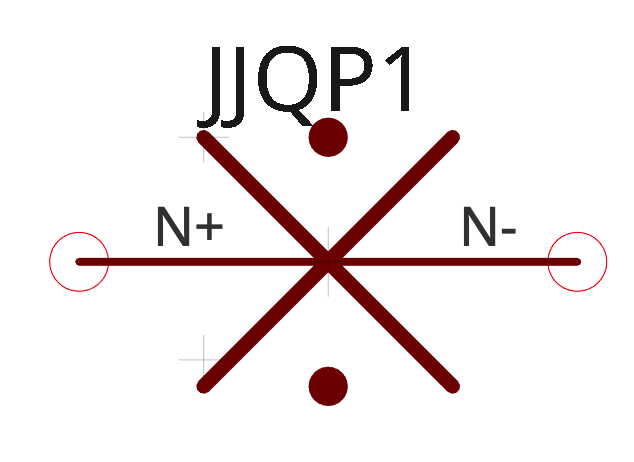 |
Includes the full physics of quasiparticles electrodynamics. Not supported by JSIM. Not supported yet by JoSIM. |
| Josephson Junction | JJ | 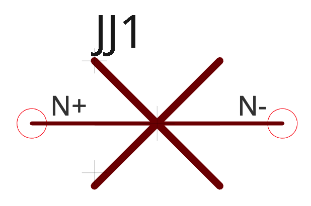 |
RTYPE=0 or 1 is supported. See documentation. RTYPE=0: JSIM default RTYPE=1:JoSIM default |
| Model | M | 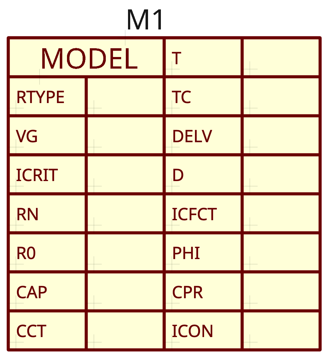 |
The .model control block is necessary to input the Josephson junction model parameters for simulations. Some of them take their default values in simulators if not specified in this block. |
| Category: | Current Sources | ||
| Current DC | I | 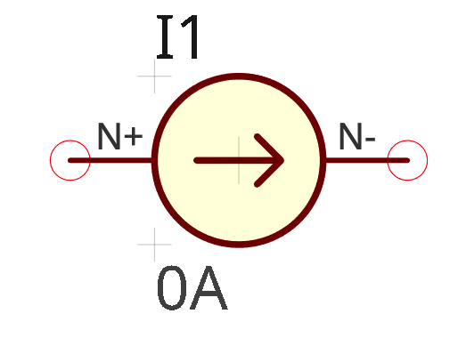 |
Not supported by JSIM. Automatically transformed in the corresponding IPWL source during L2SPICE conversion. |
| Current AC | ISIN | 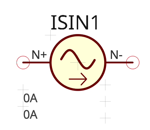 |
The I0 DC value must be 0 for JSIM. Non-zero values are automatically set to 0 for JSIM netlists during L2SPICE conversion. The THETA parameter is the inverse of a time constant. It should be negative in JSIM (error in the simulator code) for an attenuated sinusoidal signal. |
| Current Pulse | IPULSE | 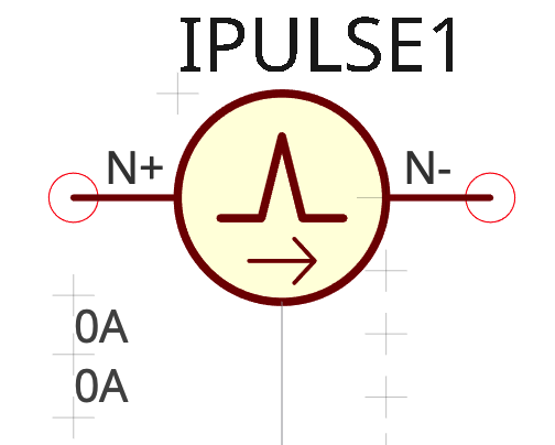 |
The I1 minimum current value must be 0 for JSIM. Non-zero values are automatically set to 0 for JSIM netlists during L2SPICE conversion. The PER parameter of pulses repetition rate must be different from 0 for JSIM and in any case higher that the total pulse width TR+TF+PW. L2SPICE automatically sets PER to TR+TF+PW+5ps during conversion in JSIM netlists. |
| Current PWL | IPWL | 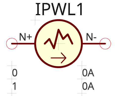 |
|
| Current Relaxation | IRELAX | 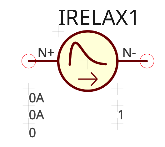 |
Not supported by JSIM. |
| Current Noise | INOISE | 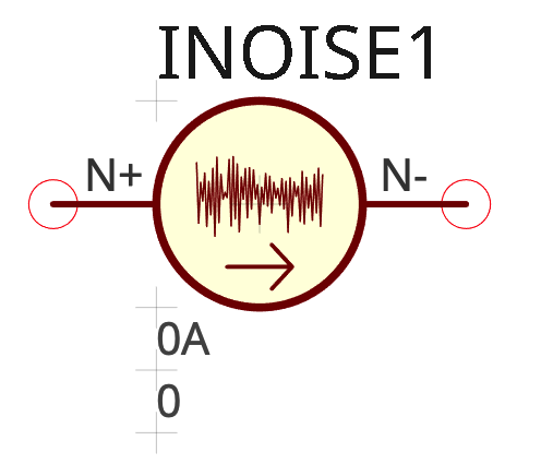 |
|
| Current Custom Waveform | ICUSTOM | 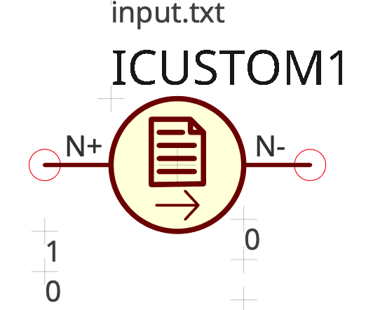 |
Not supported by JSIM. The waveform is in the input.txt file. The name input.txt is a variable that can be customised in the component. |
| Category: | Voltage Sources | ||
| Voltage DC | V | 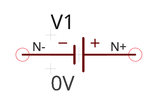 |
Not supported by JSIM. Automatically transformed in the corresponding VPWL source during L2SPICE conversion. |
| Voltage AC | VSIN | 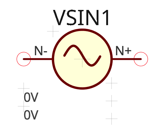 |
The V0 DC value must be 0 for JSIM. Non-zero values are automatically set to 0 for JSIM netlists during L2SPICE conversion. The THETA parameter is the inverse of a time constant. It should be negative in JSIM (error in the simulator code) for an attenuated sinusoidal signal. |
| Voltage Pulse | VPULSE | 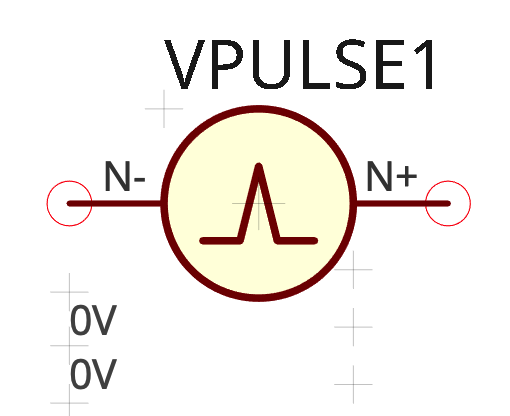 |
The V1 minimum current value must be 0 for JSIM. Non-zero values are automatically set to 0 for JSIM netlists during L2SPICE conversion. The PER parameter of pulses repetition rate must be different from 0 for JSIM and in any case higher that the total pulse width TR+TF+PW. L2SPICE automatically sets PER to TR+TF+PW+5ps during conversion in JSIM netlists. |
| Voltage PWL | VPWL |  |
|
| Voltage Relaxation | VRELAX |  |
Not supported by JSIM. |
| Voltage Noise | VNOISE |  |
|
| Voltage Custom Waveform | VCUSTOM |  |
Not supported by JSIM. The waveform is in the input.txt file. The name input.txt is a variable that can be customised in the component. |
| Category: | Phase Sources | Supported by JoSIM only | |
| Phase DC | PH | 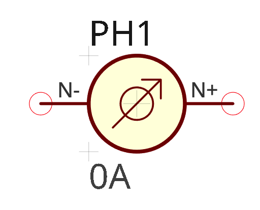 |
Not supported by JSIM. |
| Phase AC | PHSIN | 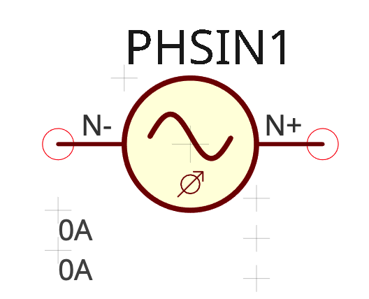 |
Not supported by JSIM. |
| Phase Pulse | PHPULSE | 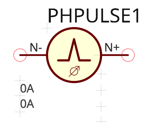 |
Not supported by JSIM. |
| Phase PWL | PHPWL | 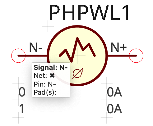 |
Not supported by JSIM. |
| Phase Relaxation | PHRELAX | 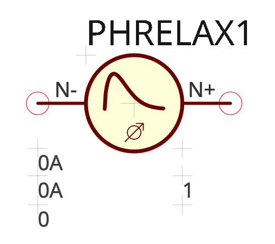 |
Not supported by JSIM. |
| Phase Noise | PHNOISE | 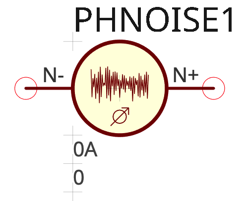 |
Not supported by JSIM. |
| Phase Custom Waveform | PHCUSTOM | 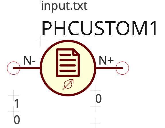 |
Not supported by JSIM. The waveform is in the input.txt file. The name input.txt is a variable that can be customised in the component. |
| Category: | Measurement Devices | ||
| Voltmeter | VOLT | 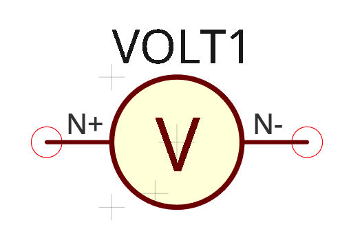 |
|
| Ammeter | CURR | 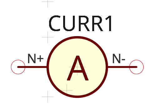 |
The current ammeter must be placed, unlike in a real experimentaal circuit, in parallel with the branch where the current should be sensed. |
| Phasemeter | PHASE | 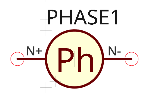 |
|
| Voltage Probe | VPROBE | 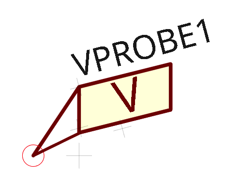 |
VProbe measures the voltage difference with respect to the Ground voltage. |
| Phase Probe | PHPROBE |  |
\(\phi\)Probe measures the phase difference with respect to the Ground phase. |
| Category: | Passive devices | ||
| Capacitor | C | 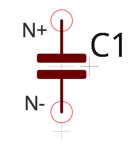 |
|
| Resistor | R |  |
|
| Inductor | L |  |
|
| Mutual Inductance | K |  |
Requires the presence in the circuit of the two coupled inductors |
| Category: | SPICE commands | ||
| Transient Analysis | TRAN | 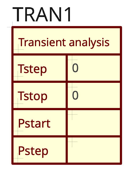 |
This control block is necessary to give the time-domain transient parameters to simulators. |
| Text | TEXT |  |
Information to pass as Comments in the SPICE netlist |
| Category: Subcircuits | |||
| Subcircuit 1 port | SUBC | 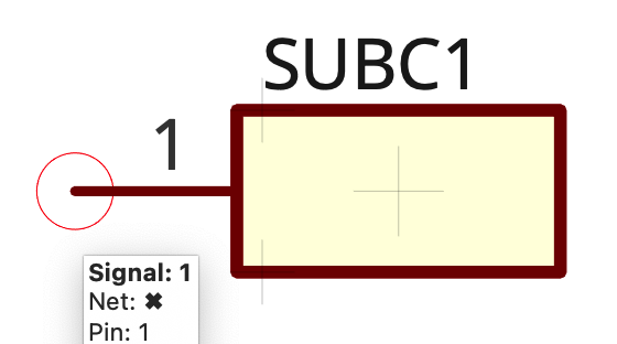 |
|
| Subcircuit 2 ports | SUBC | 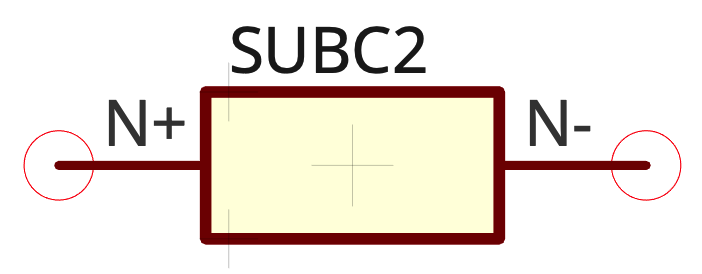 |
|
| Subcircuit 3 ports | SUBC | 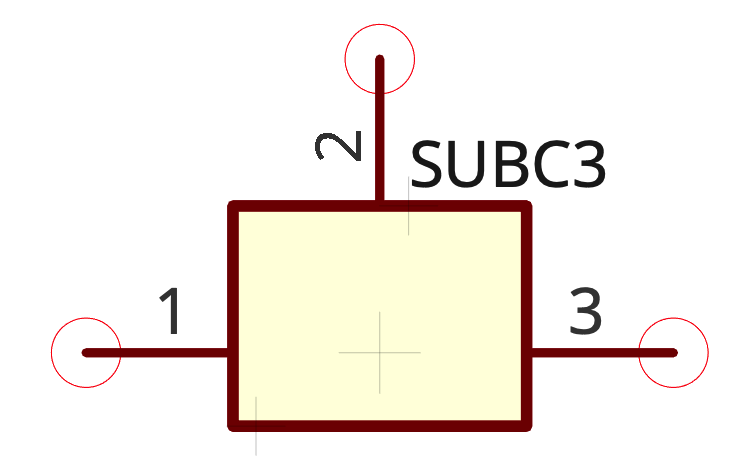 |
|
| Subcircuit 4 ports | SUBC | 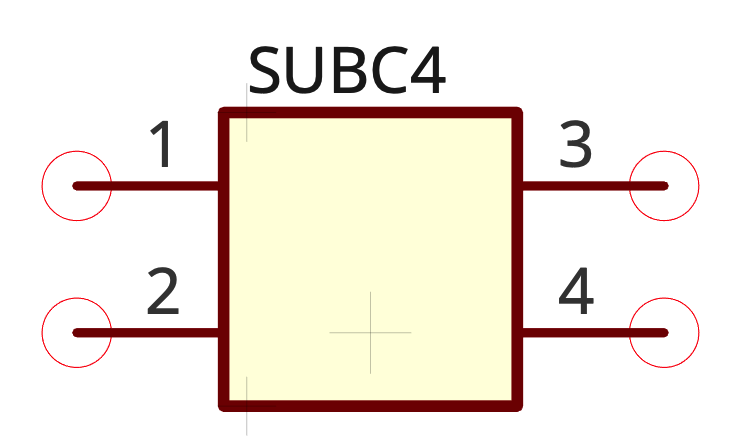 |
|
| Subcircuit 6 ports | SUBC | 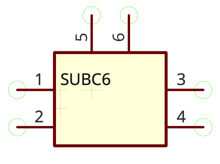 |
|
| Subcircuit 8 ports | SUBC | 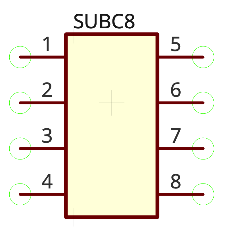 |
|
| Category: | Transmission lines | ||
| Transmission Line | T | 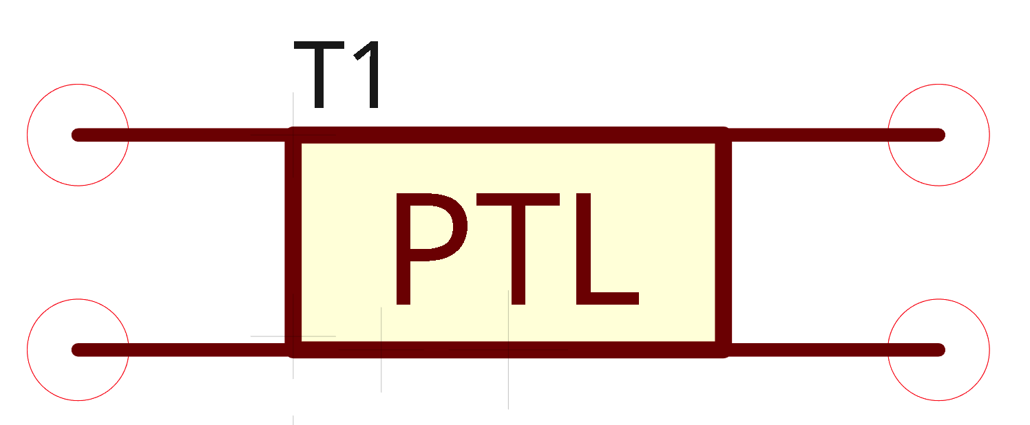 |